ENG-03 · Energy & Power
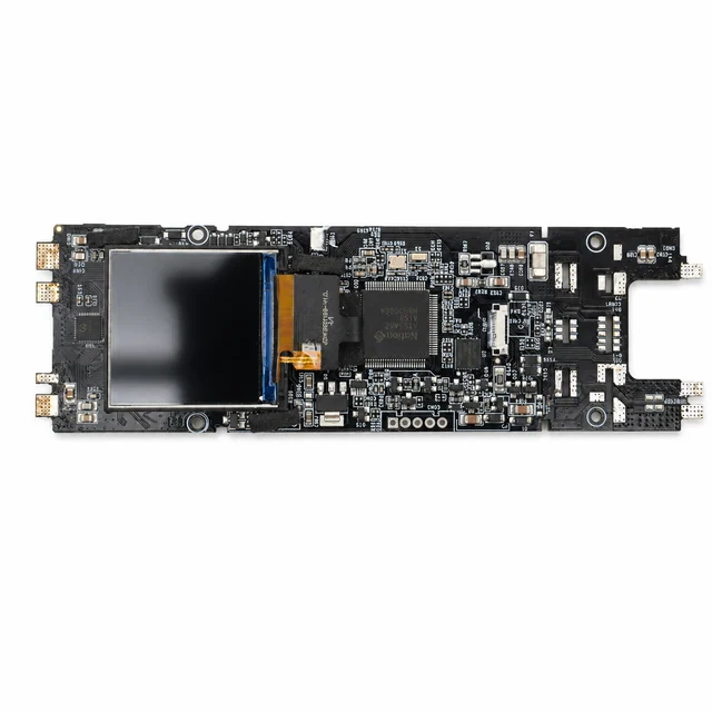
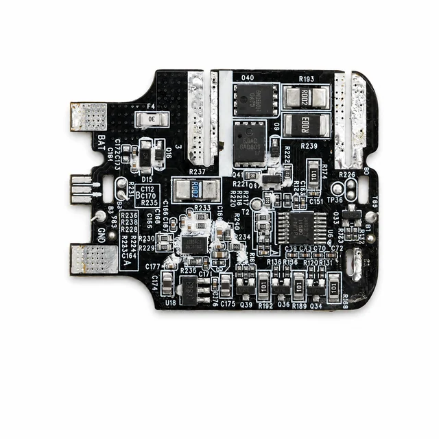
High-Power USB-C Power Bank Control PCBA
A representative portable-energy architecture for a high-output battery pack with protection, balancing, fuel gauging, multi-port power allocation, display control, and bidirectional fast charging.
Project context
A representative engineering program
A representative portable-energy architecture for a high-output battery pack with protection, balancing, fuel gauging, multi-port power allocation, display control, and bidirectional fast charging.
System architecture
How the electronics are organized
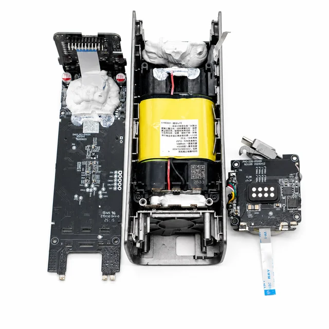
A cylindrical-cell pack connects through protection, balancing, and fuel-gauge circuitry to a shared DC bus, where multi-channel bidirectional buck-boost and USB-C power-delivery controllers manage the external ports and user interface.
Engineering risks to close
What must be resolved before release
- Allocate a high shared power budget safely across simultaneous input and output combinations.
- Limit cell, connector, inductor, and switching-device temperature inside a compact enclosure.
- Keep fuel-gauge accuracy, role swapping, cable detection, and protection states consistent through power interruptions.
Validation plan
Evidence expected before production
- Exercise supported USB-C profiles, cable types, role swaps, and multi-port power-allocation combinations.
- Measure conversion efficiency, ripple, connector temperature, and thermal derating from empty to full battery.
- Run cell-imbalance, overcurrent, short-circuit, charge-cycle, brownout, and interrupted-update recovery tests.
Decision-ready evidence packet
What a comparable RFQ should define
This checklist turns the technical story into reviewable inputs and release records. It describes what buyers and manufacturers should agree—not a claim that every listed record applies to every build.
Design baseline
Released schematic or block diagram, interface table, power states, critical constraints, and revision owner.
Manufacturing release
Gerber or ODB++, stack-up, centroid data, assembly drawings, approved DFM dispositions, and panel assumptions.
Material control
Released BOM revision, manufacturer part numbers, AVL or alternate rules, no-substitute lines, MSL handling, and exception approvals.
Validation record
Test method, acceptance criteria, sample or serial identity, measured result fields, and disposition. Example scope: Exercise supported USB-C profiles, cable types, role swaps, and multi-port power-allocation combinations.
Production release
First-article status plus the agreed SPI, AOI, X-ray, ICT, FCT, programming, rework, OQA, labeling, and packing records.
Project-specific fields, retention periods, sampling rules, measured limits, and customer approvals are confirmed during RFQ and protected under the applicable confidentiality agreement.
Development and production controls
Manufacturing scope represented here
- Battery protection and fuel gauging.
- Multi-channel bidirectional buck-boost.
- USB-C power delivery and display control.
Technical image review
Board-level evidence
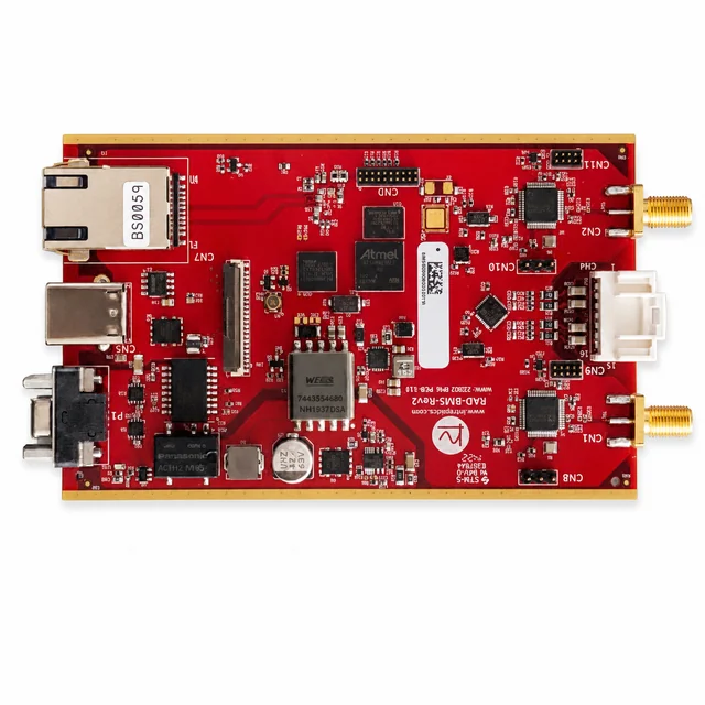
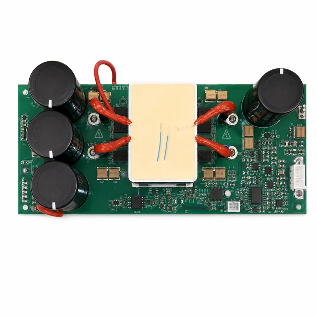
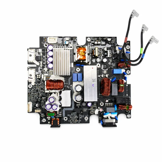
White-background views are published to make component placement, interfaces and assembly boundaries easier to inspect.