WELL-10 · Wellness Electronics
Foot-and-Leg Compression Massager Main Control PCBA
A representative mixed-actuator platform combining roller or vibration motors, air compression, warming, sensing, and wireless or panel control for foot-and-leg massage sequences.
Project context
A representative engineering program
A representative mixed-actuator platform combining roller or vibration motors, air compression, warming, sensing, and wireless or panel control for foot-and-leg massage sequences.
System architecture
How the electronics are organized
A low-voltage input feeds logic and protected motor, pump, valve, and heater outputs; an MCU coordinates pressure, current, temperature, position, and user-interface states through multiple harness connections.
Engineering risks to close
What must be resolved before release
- Budget simultaneous pump startup, motor stall, valve current, and cold-heater load.
- Map many color-coded harnesses and pneumatic channels without assembly ambiguity.
- Release the leg safely after overpressure, valve fault, low voltage, or controller reset.
Validation plan
Evidence expected before production
- Map every connector and pneumatic path before running per-channel voltage, current, direction, and feedback tests.
- Record chamber pressure rise, peak, hold leakage, release time, and blocked or leaking tube responses.
- Test combined-load thermal rise, supply droop, motor stall, NTC faults, and wireless loss.
Decision-ready evidence packet
What a comparable RFQ should define
This checklist turns the technical story into reviewable inputs and release records. It describes what buyers and manufacturers should agree—not a claim that every listed record applies to every build.
Design baseline
Released schematic or block diagram, interface table, power states, critical constraints, and revision owner.
Manufacturing release
Gerber or ODB++, stack-up, centroid data, assembly drawings, approved DFM dispositions, and panel assumptions.
Material control
Released BOM revision, manufacturer part numbers, AVL or alternate rules, no-substitute lines, MSL handling, and exception approvals.
Validation record
Test method, acceptance criteria, sample or serial identity, measured result fields, and disposition. Example scope: Map every connector and pneumatic path before running per-channel voltage, current, direction, and feedback tests.
Production release
First-article status plus the agreed SPI, AOI, X-ray, ICT, FCT, programming, rework, OQA, labeling, and packing records.
Project-specific fields, retention periods, sampling rules, measured limits, and customer approvals are confirmed during RFQ and protected under the applicable confidentiality agreement.
Development and production controls
Manufacturing scope represented here
- Mixed motor, pump, valve, and heater control.
- Pressure, temperature, and current supervision.
- Wireless or local sequence management.
Technical image review
Board-level evidence
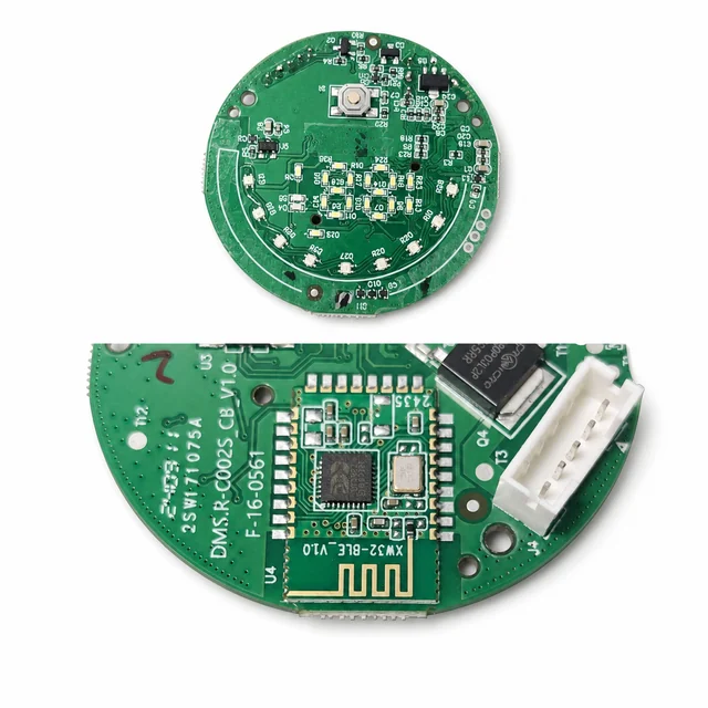
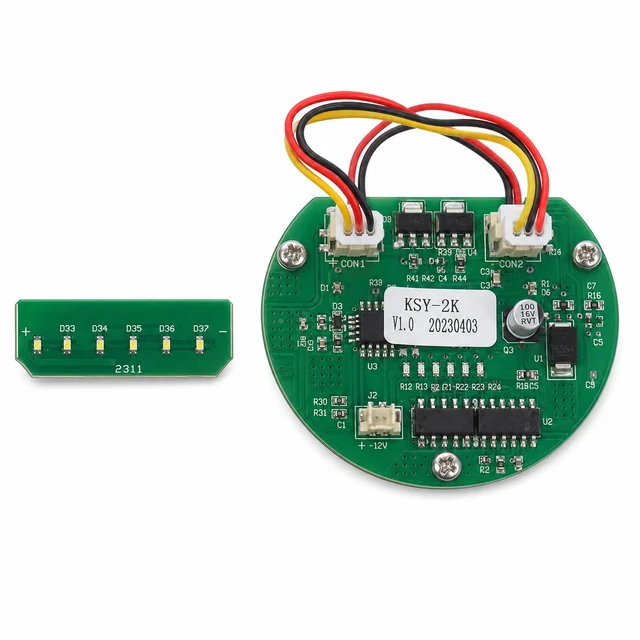
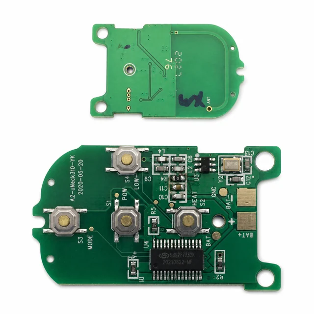
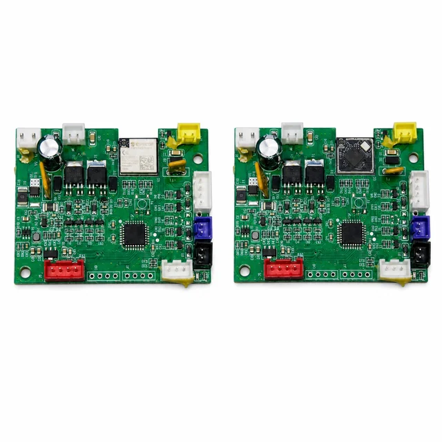
White-background views are published to make component placement, interfaces and assembly boundaries easier to inspect.