WELL-01 · Wellness Electronics
Smart High-Torque Percussion Massager PCBA
A representative development architecture for a high-output percussion massager with controlled motor startup, speed or load supervision, battery management, local indication, and optional wireless control.
Project context
A representative engineering program
A representative development architecture for a high-output percussion massager with controlled motor startup, speed or load supervision, battery management, local indication, and optional wireless control.
System architecture
How the electronics are organized
A battery and BMS feed a separate high-current motor stage, while an MCU coordinates commutation or PWM control, current and temperature feedback, a display interface, and optional BLE communication.
Engineering risks to close
What must be resolved before release
- Control high startup and stall current without resetting the logic or overheating the power stage.
- Maintain useful speed or force as battery voltage and applied load change.
- Protect wireless performance and interconnects in a high-vibration, high-current enclosure.
Validation plan
Evidence expected before production
- Measure no-load and controlled-load speed, current, noise, and thermal rise across battery states.
- Exercise limited-energy stall, overload, low-voltage, and charge-interlock fault responses.
- Run vibration endurance while monitoring connectors, fasteners, display operation, and wireless range.
Decision-ready evidence packet
What a comparable RFQ should define
This checklist turns the technical story into reviewable inputs and release records. It describes what buyers and manufacturers should agree—not a claim that every listed record applies to every build.
Design baseline
Released schematic or block diagram, interface table, power states, critical constraints, and revision owner.
Manufacturing release
Gerber or ODB++, stack-up, centroid data, assembly drawings, approved DFM dispositions, and panel assumptions.
Material control
Released BOM revision, manufacturer part numbers, AVL or alternate rules, no-substitute lines, MSL handling, and exception approvals.
Validation record
Test method, acceptance criteria, sample or serial identity, measured result fields, and disposition. Example scope: Measure no-load and controlled-load speed, current, noise, and thermal rise across battery states.
Production release
First-article status plus the agreed SPI, AOI, X-ray, ICT, FCT, programming, rework, OQA, labeling, and packing records.
Project-specific fields, retention periods, sampling rules, measured limits, and customer approvals are confirmed during RFQ and protected under the applicable confidentiality agreement.
Development and production controls
Manufacturing scope represented here
- Motor startup and load supervision.
- Battery, display, and wireless coordination.
- Thermal derating and fault-state control.
Technical image review
Board-level evidence
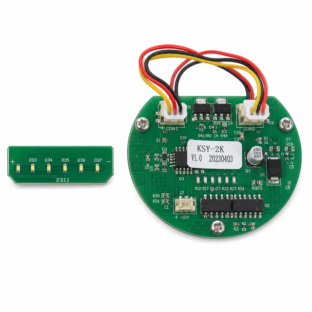
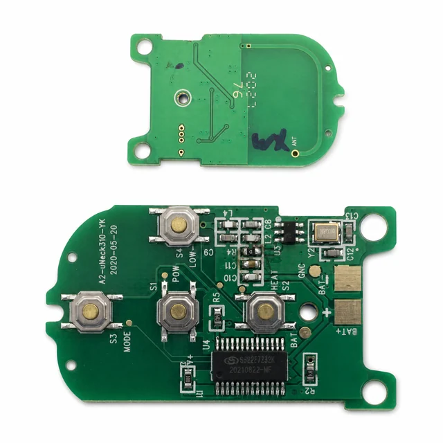
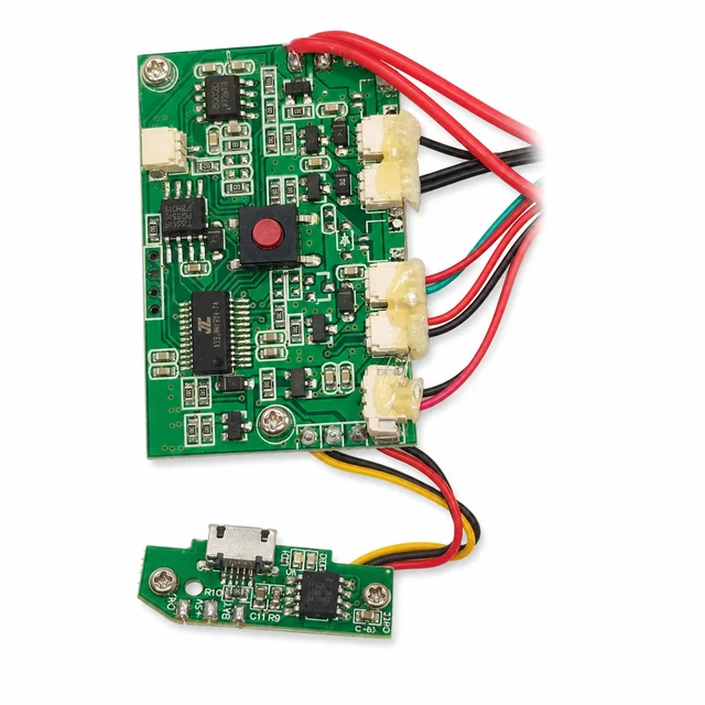
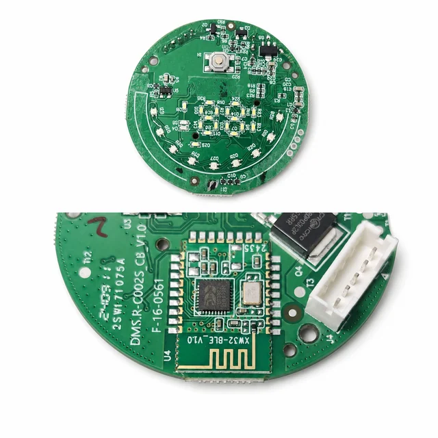
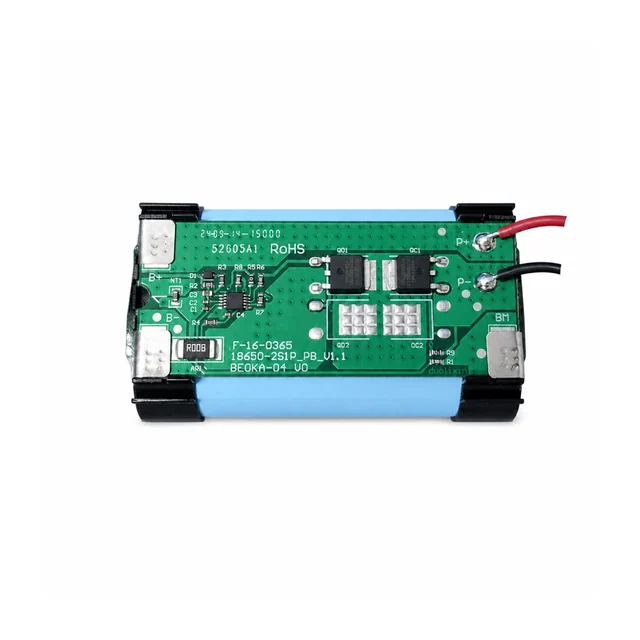
White-background views are published to make component placement, interfaces and assembly boundaries easier to inspect.