The mapping must account for wavelength, hand height, optical spread and motion. A detected rectangle alone is not a lighting boundary.
Beauty electronics · Camera-guided lighting
AI nail-lamp electronics.Vision, light and control.
A camera-guided nail-curing design that connects nail segmentation, individually controlled LED channels and timed local control. Explore the electronics behind the lighting system.

01 / System architecture
Separate vision from real-time control.
The architecture gives image processing, LED timing and hardware gating distinct responsibilities. The screen requests an operation; local control determines when lighting is permitted.
The local controller owns the timer and channel data. Three unused outputs remain off.
Power allocation, temperature inputs and fault signals form part of the illumination decision.
Find the nail contour
The software interface accepts a nail-probability map and a measured footprint for each light channel. A channel is permitted only when its complete mapped footprint falls inside the selected nail region.
Independent light commands
Seven 16-channel TLC5940 drivers provide a 112-output chain. The 109-channel allocation leaves three outputs disabled; brightness commands are bounded by the available power budget.
Keep exposure timing local
The control logic includes 9, 15 and 20-second intervals. Explicit start, stable-frame qualification, timed completion and latched faults keep the operating sequence independent of screen refresh.
A separate path to turn light off
The GUARD interface separates the lighting request from hardware permission. Watchdog recovery, output blanking, reset behavior and temperature inputs belong in one defined control sequence.
Budget the whole system
USB-C input power is shared by the processor, display, lighting and charging. The charge-current calculation reserves system power before allocating the remainder to the battery.
Make controls fit the product
The user interface can bring together mode selection, countdown, battery information and fault messages. Display dimensions, camera optics and connectivity are selected around the enclosure and product brief.
02 / Circuit views
Follow the signals through the board.
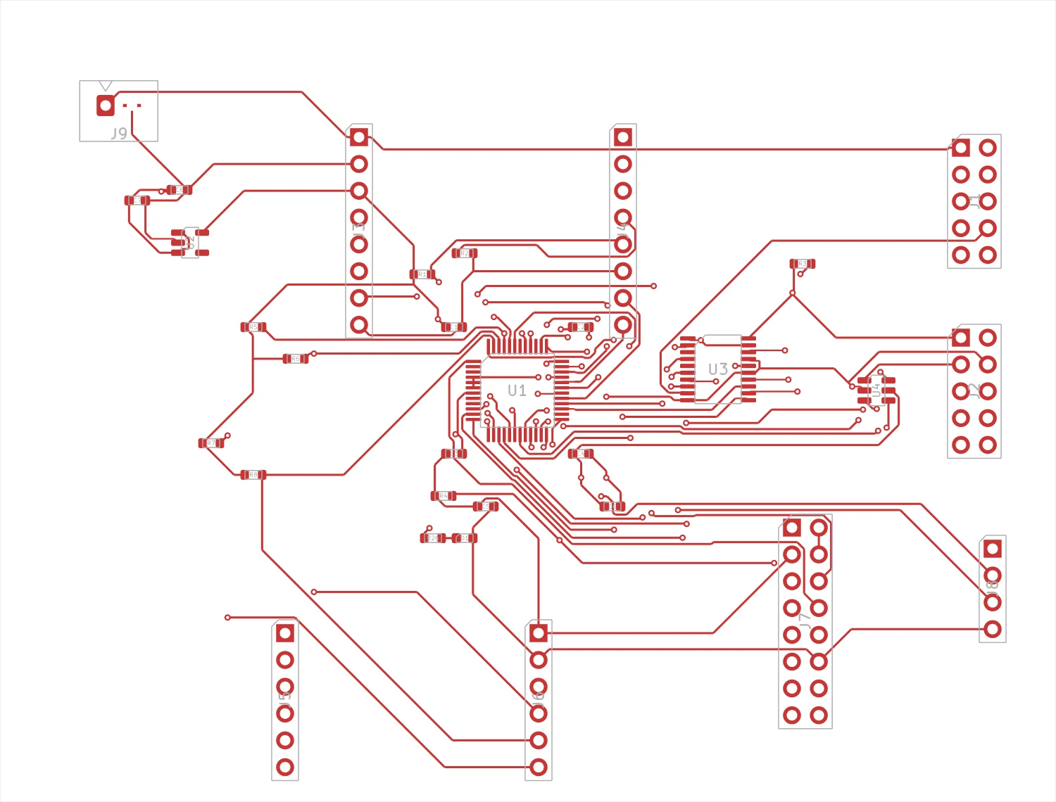
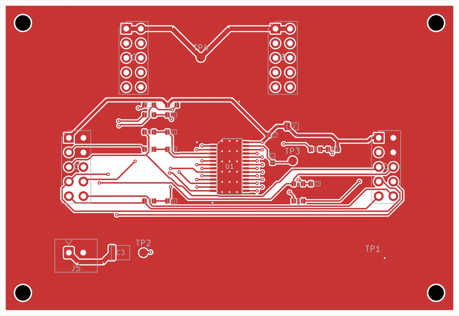
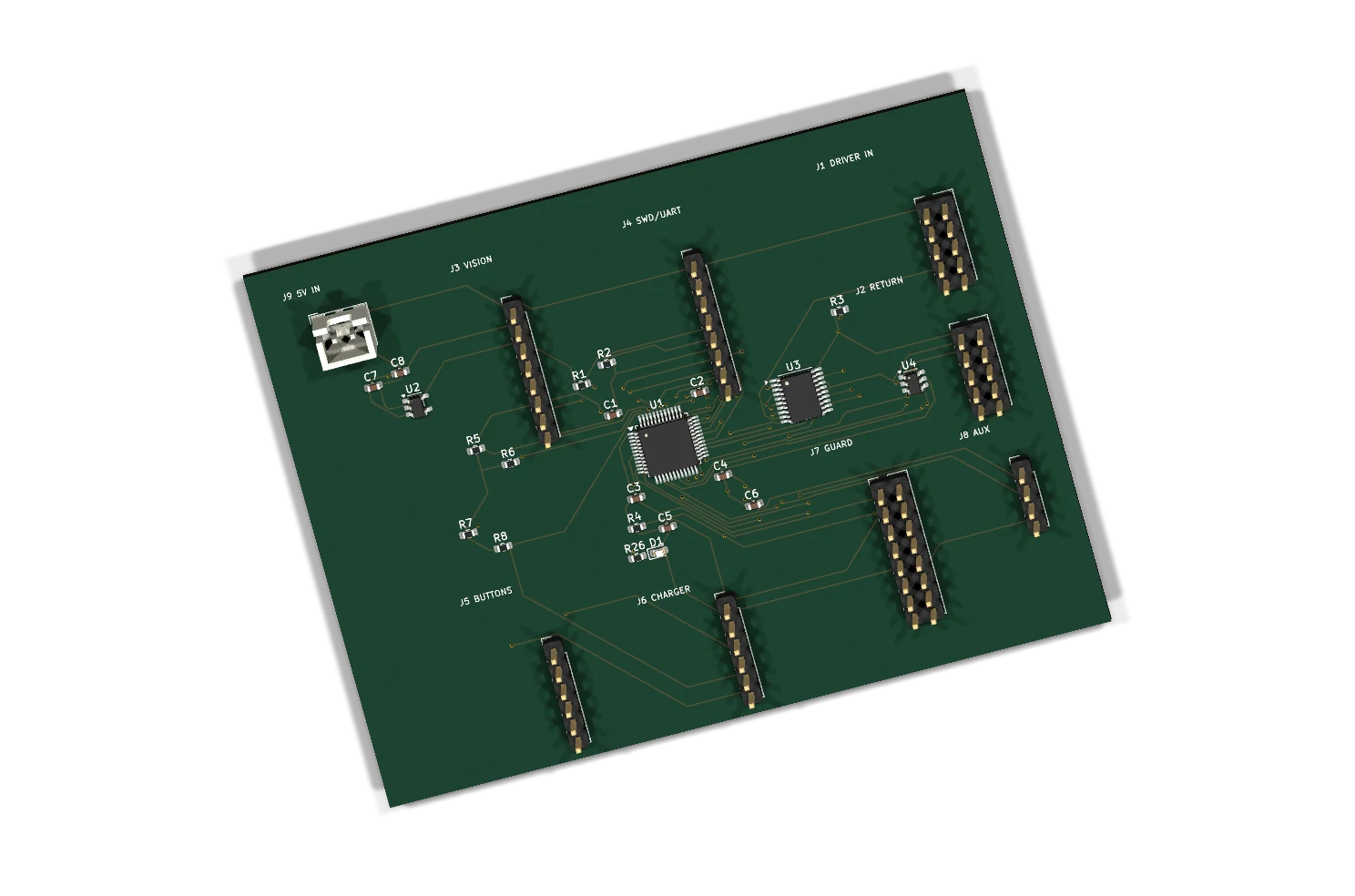
These images are exported from the editable KiCad designs. The local controller and LED driver use separate interfaces for data, timing, power and output permission.
03 / Software logic
A lighting decision has several checks.
The image-processing path proposes which channels may be used. The controller checks freshness, configuration, power and hardware permission before applying that decision.
Contour, confidence and stability
Use segmentation rather than a bounding box. High-confidence regions, an inward margin and consecutive stable frames define the software input to optical mapping.
Match the whole footprint
Compare each channel’s calibrated optical envelope with the nail region. Wavelength, hand height, camera alignment and motion allowance determine the envelope.
Reject outdated commands
The V2 message format carries a frame sequence, source age, session identifier, calibration identifier and CRC. Invalid, stale or mismatched data clears lighting permission.
Start deliberately. Stop predictably.
The controller progresses through arming, qualification and timed operation. A stop request or fault returns the outputs to the off state; a recovered fault requires a new start.
04 / Product integration
Optics and electronics define the result together.
A useful product brief connects the desired curing behavior to measurable optical, thermal and electrical requirements. Those requirements guide LED selection, board layout and the software calibration.
Wavelength, coverage and dose
Define the 365/405 nm light-source arrangement, nail-side coverage, allowed hand positions and gel-specific curing requirements. LED count alone does not define curing performance.
Start with the hand space
Camera position, LED angles, reflections, enclosure clearances and service access determine where boards and wiring can sit. Share the internal geometry together with the industrial design.
Treat charging and lighting as one load case
Specify adapter power, battery capacity, peak lighting demand and ambient temperature together. Source switching and charge termination need to account for the system load.
Review cost against the production quantity
Compare board consolidation, connector count, sourcing and test time at the required volume. Material choices and assembly scope follow the agreed electrical and optical requirements.
Your beauty-electronics project
Define your next nail-lamp controller.
Share the lighting concept, camera and screen requirements, power source, enclosure dimensions and expected quantity. Start with a product brief or attach your existing design files.
Files are optional to start. The inquiry link includes this project reference.