WELL-12 · Wellness Electronics
Hand Air-Compression Massager Control System
A representative hand-care architecture combining sequenced pneumatic compression, optional vibration and warming, an accessible LCD interface, and default pressure release.
Project context
A representative engineering program
A representative hand-care architecture combining sequenced pneumatic compression, optional vibration and warming, an accessible LCD interface, and default pressure release.
System architecture
How the electronics are organized
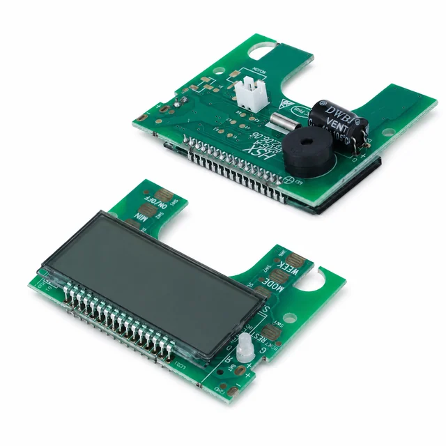
The pictured UI board handles the segmented display, key areas, buzzer, and main-board link; a separate power controller is expected to operate the pump, inlet or exhaust valves, heater, vibration motor, pressure sensing, and NTC feedback.
Engineering risks to close
What must be resolved before release
- Provide immediate release when the user's hand is enclosed.
- Prevent pump and motor noise from corrupting touch or sensor inputs.
- Hold consistent pressure and surface temperature across seal and fit variation.
Validation plan
Evidence expected before production
- Verify all LCD segments, keys, buzzer states, communication, and noise immunity on the UI board.
- Use a standard handform to measure pressure rise, peak, leakage, release time, vibration, and temperature uniformity.
- Inject pressure, valve, NTC, low-battery, and power-loss faults and run pneumatic and thermal endurance.
Decision-ready evidence packet
What a comparable RFQ should define
This checklist turns the technical story into reviewable inputs and release records. It describes what buyers and manufacturers should agree—not a claim that every listed record applies to every build.
Design baseline
Released schematic or block diagram, interface table, power states, critical constraints, and revision owner.
Manufacturing release
Gerber or ODB++, stack-up, centroid data, assembly drawings, approved DFM dispositions, and panel assumptions.
Material control
Released BOM revision, manufacturer part numbers, AVL or alternate rules, no-substitute lines, MSL handling, and exception approvals.
Validation record
Test method, acceptance criteria, sample or serial identity, measured result fields, and disposition. Example scope: Verify all LCD segments, keys, buzzer states, communication, and noise immunity on the UI board.
Production release
First-article status plus the agreed SPI, AOI, X-ray, ICT, FCT, programming, rework, OQA, labeling, and packing records.
Project-specific fields, retention periods, sampling rules, measured limits, and customer approvals are confirmed during RFQ and protected under the applicable confidentiality agreement.
Development and production controls
Manufacturing scope represented here
- Segmented-display and key integration.
- Pump, valve, vibration, and heater system planning.
- Default release and timed-session control.
Technical image review
Board-level evidence
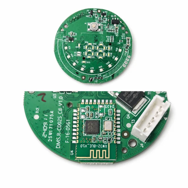
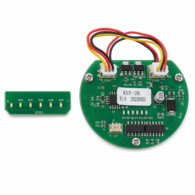
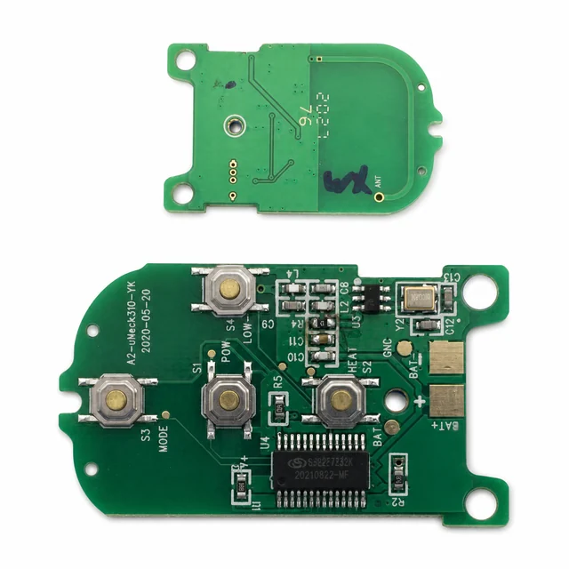
White-background views are published to make component placement, interfaces and assembly boundaries easier to inspect.