Battery, charge and motor control
The PCB combines a 3S battery-protection circuit, USB-C PD charging and motor switching. The actual cells, pump head and cell-proximate fuse connect externally.
ENGINEERING REFERENCE · V0.5
Engineering sample · Performance testing pending
One board for the controller, USB-C charging, motor drive, 3S battery protection, LCD driver and five keys. An engineering sample design with public CAD files; performance awaits physical testing.
175 × 160 mm · 4 layers · 1.6 mm · 225 functional components
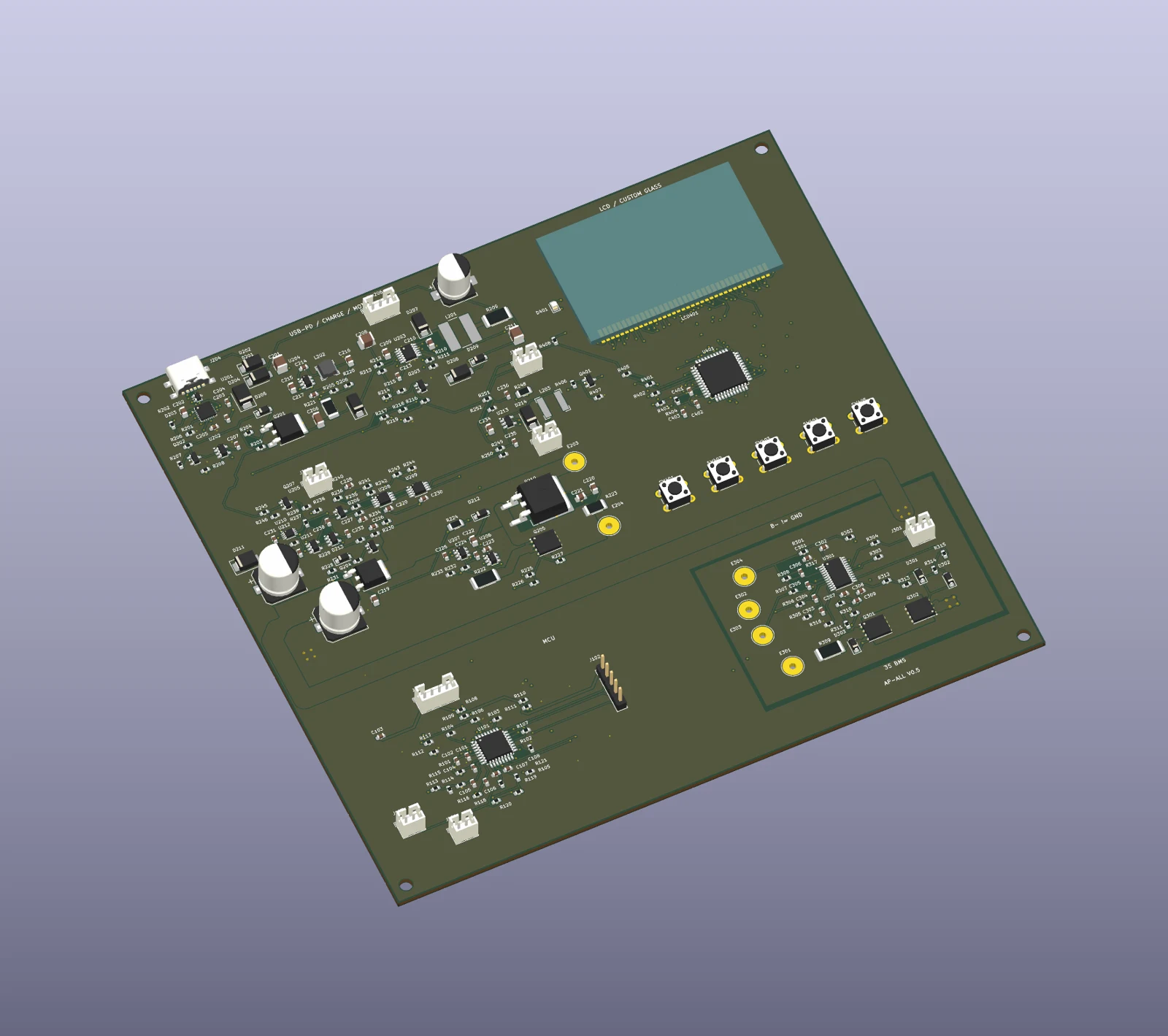
The PCB combines a 3S battery-protection circuit, USB-C PD charging and motor switching. The actual cells, pump head and cell-proximate fuse connect externally.
An HT1621 segment-LCD driver, backlight circuit and five keys are onboard. The proposed 52 × 32 mm glass mounts directly to the PCB. The illumination driver connects to an external LED and thermal assembly.
Start/stop, mode, pressure adjustment and lighting have dedicated keys. Firmware V0.6 implements preset stopping, unit switching and persistent settings; real-board verification is pending.
This first integrated version retains space for debugging. Its 175 × 160 mm outline has not been reduced to fit a final enclosure. Images show the CAD layout, not a manufactured assembly.
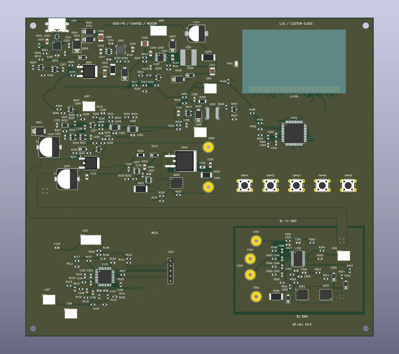
The saved KiCad 10.0.6 reports record zero configured ERC violations, zero DRC violations, zero unconnected items and zero schematic/PCB parity issues. An independent comparison matched 678 numbered-pad keys and all 225 functional footprints.
These are file-level checks. They do not establish pump output, temperature rise, charging safety or manufacturing approval. The package records the configured ERC exclusions.
V0.5 project, 23 schematic pages, routed PCB, local libraries, BOM, interfaces, LCD segment proposal, CAD reports and Gerber review files. Chinese engineering notes are included.
Download the complete engineering packageControl logic, HT1621 display, five keys, mode memory, PD gating and fault handling are implemented. 50 host tests and the ARM target build pass. The supplied BIN/HEX locks motor and charging outputs; physical calibration and commissioning remain pending.
Source, offline CMSIS headers, bench ELF/BIN/HEX, build instructions, pin map, operating notes and validation records. Hardware remains V0.5.
Download firmware V0.6100 W, 12 A continuous current and 150 psi are design targets, with no physical performance results available. The custom LCD, exact pump and sensor parts, final mechanics, full-load and stall behavior, thermal performance, firmware integration and pressure calibration remain open.
Control logic, HT1621 display, five keys, mode memory, PD gating and fault handling are implemented. 50 host tests and the ARM target build pass. The supplied BIN/HEX locks motor and charging outputs; physical calibration and commissioning remain pending. MCU charging-status feedback is absent; no inferred charge-complete indication.