HOME-04 · Connected Home
Connected Mains Switch and DIN-Rail Control PCBA
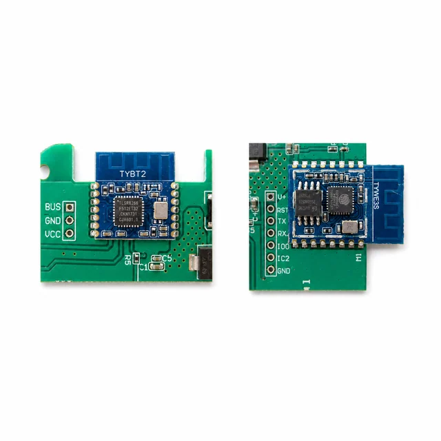
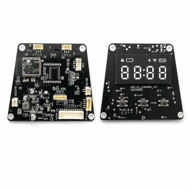
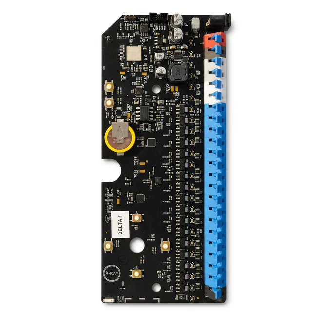
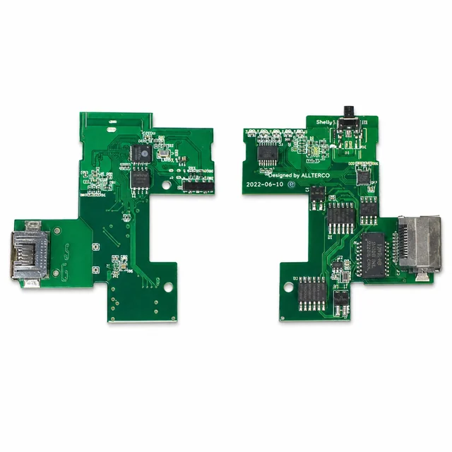
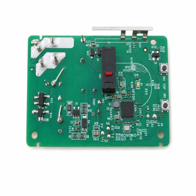
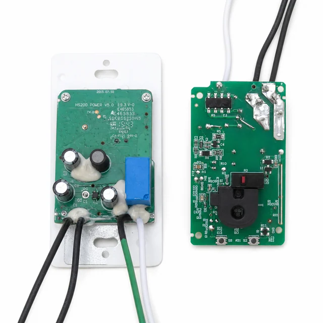
An FCC-photo reference combining a wall-switch power and control assembly with visible antenna placement and a separate connected control-board example featuring an RJ45-form interface.
Project context
A representative engineering program
An FCC-photo reference combining a wall-switch power and control assembly with visible antenna placement and a separate connected control-board example featuring an RJ45-form interface.
System architecture
How the electronics are organized
A representative design conditions mains power, generates a control rail, reads local inputs, and commands a relay or solid-state switch through the product's required insulation strategy; connected variants may add Wi-Fi and wired Ethernet control.
Engineering risks to close
What must be resolved before release
- Meet shock-protection, creepage, clearance, surge, and enclosure requirements in a confined wall box.
- Control relay inrush, contact arcing, leakage, and temperature rise across diverse lighting loads.
- Preserve local switching and authenticated state control when network or cloud services fail.
Validation plan
Evidence expected before production
- Test resistive, LED, and motor-like load inrush, rapid cycling, contact endurance, and full-load temperature rise.
- Perform applicable dielectric, insulation, miswire, single-fault, surge, EFT, ESD, conducted, and radiated testing.
- Verify metal-box RF performance, local-control fallback, command replay resistance, and interrupted-update recovery.
Decision-ready evidence packet
What a comparable RFQ should define
This checklist turns the technical story into reviewable inputs and release records. It describes what buyers and manufacturers should agree—not a claim that every listed record applies to every build.
Design baseline
Released schematic or block diagram, interface table, power states, critical constraints, and revision owner.
Manufacturing release
Gerber or ODB++, stack-up, centroid data, assembly drawings, approved DFM dispositions, and panel assumptions.
Material control
Released BOM revision, manufacturer part numbers, AVL or alternate rules, no-substitute lines, MSL handling, and exception approvals.
Validation record
Test method, acceptance criteria, sample or serial identity, measured result fields, and disposition. Example scope: Test resistive, LED, and motor-like load inrush, rapid cycling, contact endurance, and full-load temperature rise.
Production release
First-article status plus the agreed SPI, AOI, X-ray, ICT, FCT, programming, rework, OQA, labeling, and packing records.
Project-specific fields, retention periods, sampling rules, measured limits, and customer approvals are confirmed during RFQ and protected under the applicable confidentiality agreement.
Development and production controls
Manufacturing scope represented here
- Mains load switching.
- Wireless and wired control integration.
- Local HMI and power-stage coordination.
Technical image review
Board-level evidence
White-background views are published to make component placement, interfaces and assembly boundaries easier to inspect.