HOME-08 · Connected Home
Dual-Zone Smart Mattress Thermal Control PCBA
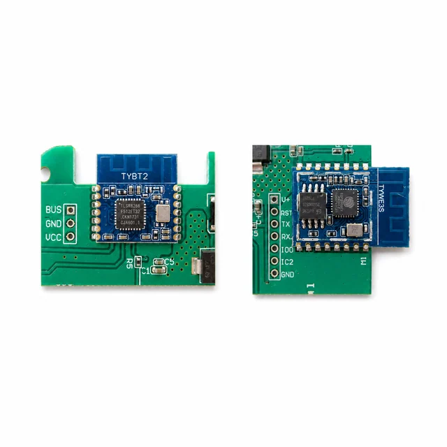
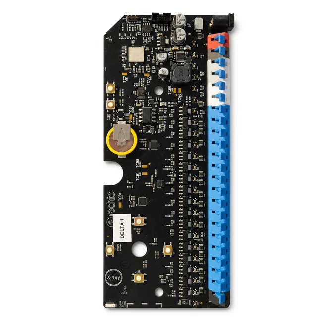
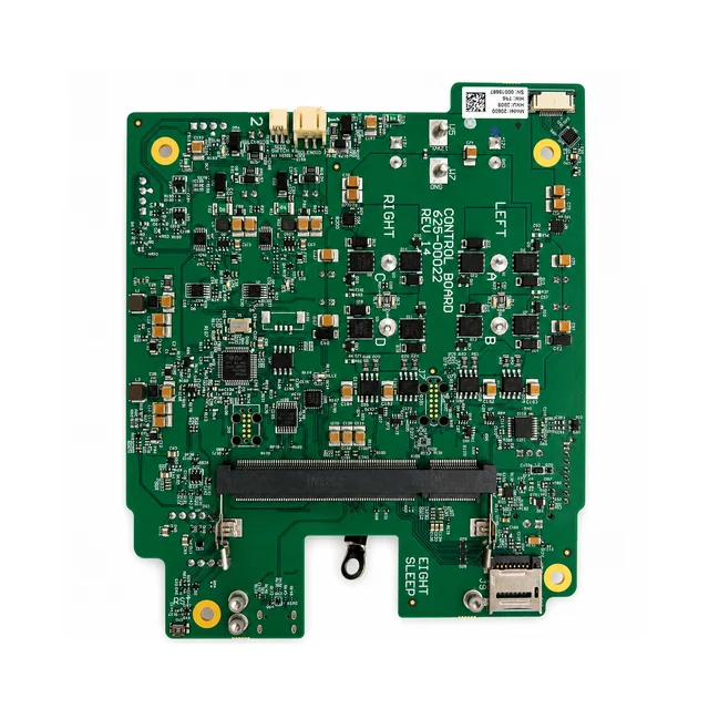
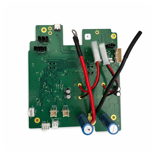
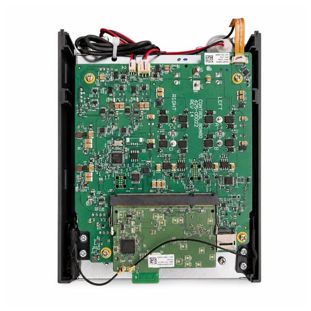
An FCC-photo reference showing a 12 V control board with mirrored left and right power channels, labeled pump, fan, solenoid and reed-switch connectors, plus a separate SOM and antenna assembly.
Project context
A representative engineering program
An FCC-photo reference showing a 12 V control board with mirrored left and right power channels, labeled pump, fan, solenoid and reed-switch connectors, plus a separate SOM and antenna assembly.
System architecture
How the electronics are organized
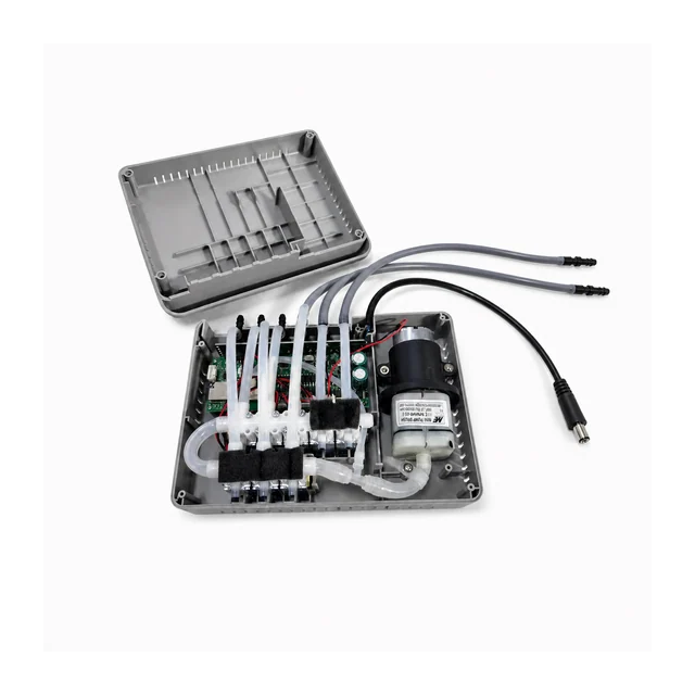
A typical dual-zone hub uses a real-time MCU to regulate pumps, fans, and valves from a protected 12 V bus while a separate SOM manages networking, data services, and updates; local temperature and flow safeguards remain available if the SOM disconnects.
Engineering risks to close
What must be resolved before release
- Coordinate two fluid and airflow zones with low noise, bounded temperature, and stable startup current.
- Detect pump, fan, valve, flow, temperature, condensation, and leak faults during long unattended operation.
- Isolate real-time safety behavior from higher-level connectivity or update failures.
Validation plan
Evidence expected before production
- Test input dips, output shorts, blocked or reverse-driven loads, thermal rise, and SOM communication loss.
- Exercise air removal, dry operation, flow anomalies, leak and condensation exposure, and sensor open or short faults.
- Measure acoustic performance, actuator life, wireless coexistence, transport vibration, ESD, EFT, and power-loss recovery.
Decision-ready evidence packet
What a comparable RFQ should define
This checklist turns the technical story into reviewable inputs and release records. It describes what buyers and manufacturers should agree—not a claim that every listed record applies to every build.
Design baseline
Released schematic or block diagram, interface table, power states, critical constraints, and revision owner.
Manufacturing release
Gerber or ODB++, stack-up, centroid data, assembly drawings, approved DFM dispositions, and panel assumptions.
Material control
Released BOM revision, manufacturer part numbers, AVL or alternate rules, no-substitute lines, MSL handling, and exception approvals.
Validation record
Test method, acceptance criteria, sample or serial identity, measured result fields, and disposition. Example scope: Test input dips, output shorts, blocked or reverse-driven loads, thermal rise, and SOM communication loss.
Production release
First-article status plus the agreed SPI, AOI, X-ray, ICT, FCT, programming, rework, OQA, labeling, and packing records.
Project-specific fields, retention periods, sampling rules, measured limits, and customer approvals are confirmed during RFQ and protected under the applicable confidentiality agreement.
Development and production controls
Manufacturing scope represented here
- Independent dual-zone actuation.
- Real-time MCU and SOM partitioning.
- Pump, fan, valve, and sensor integration.
Technical image review
Board-level evidence
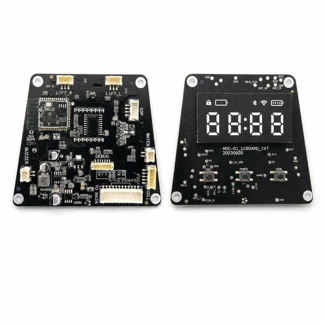
White-background views are published to make component placement, interfaces and assembly boundaries easier to inspect.