HOME-12 · Connected Home
Smart Humidifier Display and Actuator PCBA Set
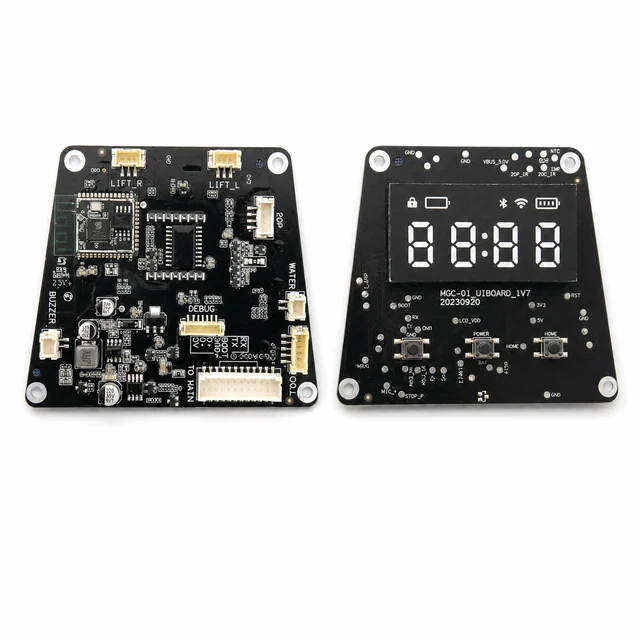
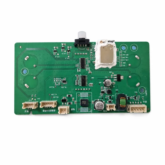
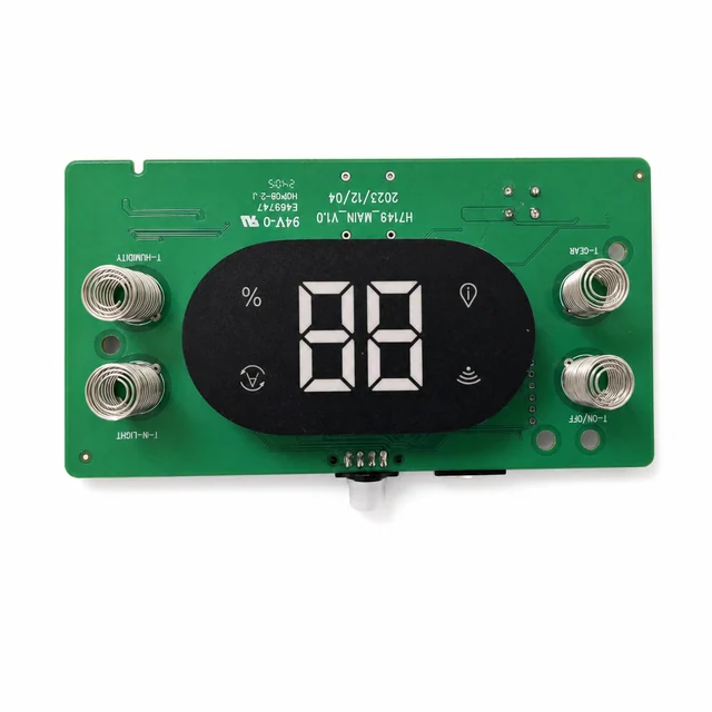
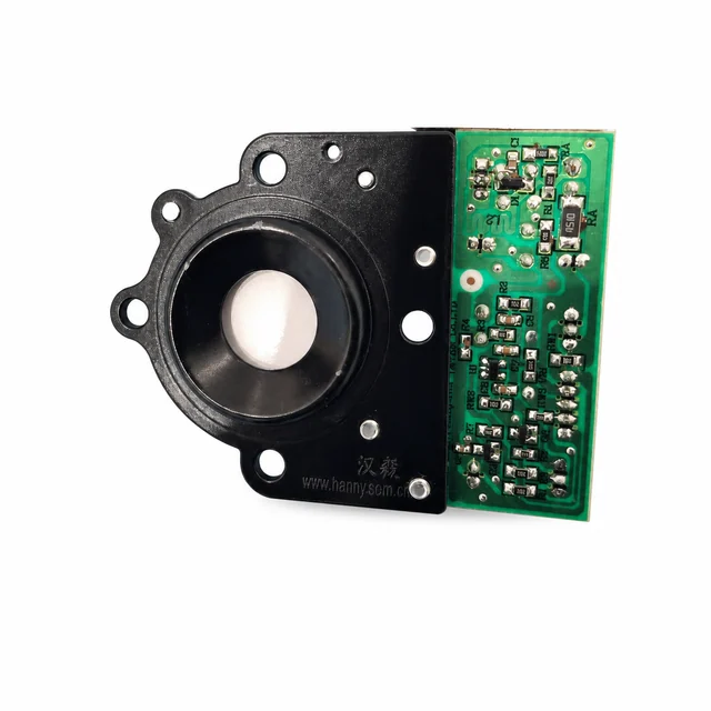
An FCC-photo reference showing an H7149 fan or airflow sub-board and a main display board with dual-digit indication, humidity and wireless icons, and four spring-touch electrodes.
Project context
A representative engineering program
An FCC-photo reference showing an H7149 fan or airflow sub-board and a main display board with dual-digit indication, humidity and wireless icons, and four spring-touch electrodes.
System architecture
How the electronics are organized
A representative low-voltage system reads humidity, water-level, temperature, and touch inputs, then coordinates a fan, display, lighting, and a protected humidification power stage; the exact atomization and radio implementations remain configuration-dependent.
Engineering risks to close
What must be resolved before release
- Shut down safely for low water, abnormal resonance, fan stall, over-temperature, or sensor disagreement.
- Keep mist, condensation, scale, and cleaning agents away from connectors, touch nodes, power electronics, and sensing surfaces.
- Prevent high-frequency drive noise and wet-hand touch events from disturbing humidity readings or control stability.
Validation plan
Evidence expected before production
- Inject low-water, overfill, tilt, leak, fan-stall, atomizer open or short, temperature, and humidity-sensor faults.
- Measure humidity accuracy, control hysteresis, cold-condensation recovery, wet-hand touch behavior, noise, and 24-hour cycling.
- Run scale and cleaning-agent exposure, corrosion, low-voltage startup, ESD, EFT, emissions, and interrupted-update tests.
Decision-ready evidence packet
What a comparable RFQ should define
This checklist turns the technical story into reviewable inputs and release records. It describes what buyers and manufacturers should agree—not a claim that every listed record applies to every build.
Design baseline
Released schematic or block diagram, interface table, power states, critical constraints, and revision owner.
Manufacturing release
Gerber or ODB++, stack-up, centroid data, assembly drawings, approved DFM dispositions, and panel assumptions.
Material control
Released BOM revision, manufacturer part numbers, AVL or alternate rules, no-substitute lines, MSL handling, and exception approvals.
Validation record
Test method, acceptance criteria, sample or serial identity, measured result fields, and disposition. Example scope: Inject low-water, overfill, tilt, leak, fan-stall, atomizer open or short, temperature, and humidity-sensor faults.
Production release
First-article status plus the agreed SPI, AOI, X-ray, ICT, FCT, programming, rework, OQA, labeling, and packing records.
Project-specific fields, retention periods, sampling rules, measured limits, and customer approvals are confirmed during RFQ and protected under the applicable confidentiality agreement.
Development and production controls
Manufacturing scope represented here
- Humidity and water-state control.
- Display and spring-touch HMI.
- Fan and humidification-stage coordination.
Technical image review
Board-level evidence
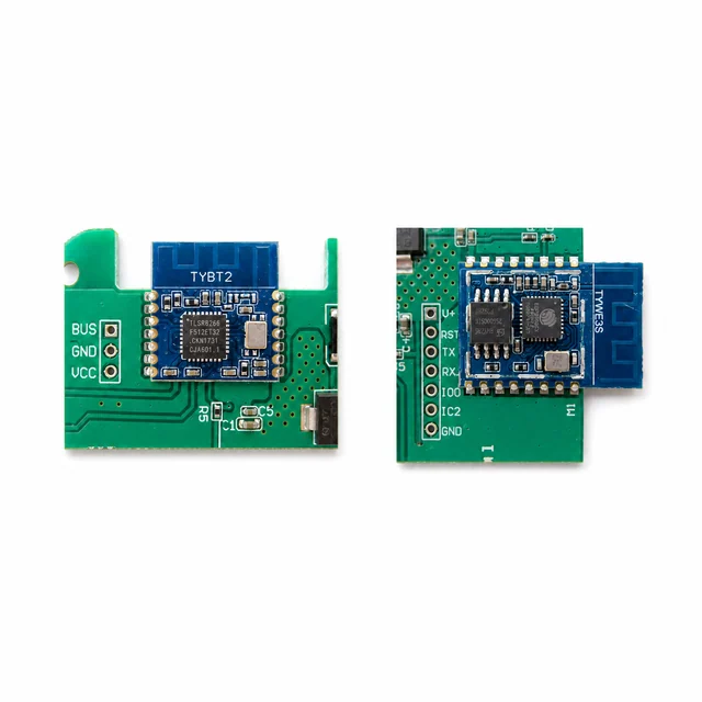
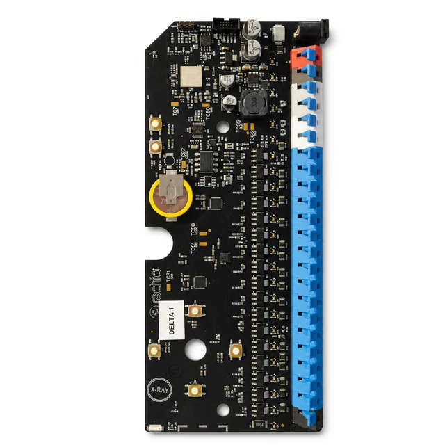
White-background views are published to make component placement, interfaces and assembly boundaries easier to inspect.