HOME-13 · Connected Home
Multi-Channel Home Energy Monitor PCBA
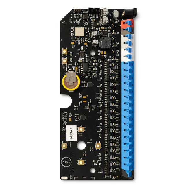
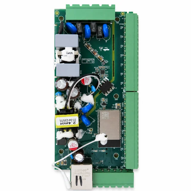
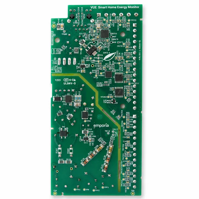
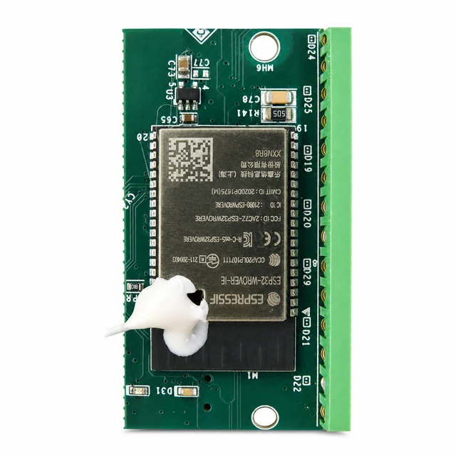
An FCC-photo reference showing an EMV3-A board with repeated current-transformer input channels, voltage-sensing components, isolation slots, dense test access, and an ESP32-WROVER-IE module with external antenna.
Project context
How this product is typically engineered
An FCC-photo reference showing an EMV3-A board with repeated current-transformer input channels, voltage-sensing components, isolation slots, dense test access, and an ESP32-WROVER-IE module with external antenna.
System architecture
Typical architecture
A representative monitor derives protected low-voltage power, conditions line-voltage references and multiple CT signals, synchronously samples the channels, computes RMS, power factor and accumulated energy, and reports results through local network connectivity.
Engineering risks to resolve
Decisions to close before release
- Maintain shock protection and surge robustness while measuring small signals referenced to a mains installation.
- Control gain, phase, offset, temperature drift, saturation, and channel crosstalk across many CT inputs.
- Preserve calibration, accumulated-energy data, secure connectivity, and real-time sampling through outages and updates.
Validation plan
Checks to define before production
- Use traceable power sources to test 50 and 60 Hz, low-to-full scale, power factor, harmonics, CT reversal, offset, saturation, and crosstalk.
- Perform applicable dielectric, insulation, surge, EFT, ESD, overvoltage, terminal-misuse, single-fault, and thermal testing.
- Verify per-channel automated calibration, temperature drift, outage data consistency, network recovery, secure boot, and update rollback.
What to put in the RFQ
Files and records to agree before quoting
Use this list to agree the build inputs and release records for a similar product. The final set depends on the project.
Design baseline
Released schematic or block diagram, interface table, power states, critical constraints, and revision owner.
Manufacturing release
Gerber or ODB++, stack-up, centroid data, assembly drawings, approved DFM dispositions, and panel assumptions.
Material control
Released BOM revision, manufacturer part numbers, AVL or alternate rules, no-substitute lines, MSL handling, and exception approvals.
Validation record
Test method, acceptance criteria, sample or serial identity, measured result fields, and disposition. Example scope: Use traceable power sources to test 50 and 60 Hz, low-to-full scale, power factor, harmonics, CT reversal, offset, saturation, and crosstalk.
Production release
First-article status plus the agreed SPI, AOI, X-ray, ICT, FCT, programming, rework, OQA, labeling, and packing records.
During RFQ review, we confirm the required fields, sampling, limits, approvals, and record-retention period. Confidential project information stays within the agreed access rules.
Development and production controls
Typical manufacturing scope
- Scalable multi-channel CT measurement.
- Voltage-current phase and energy computation.
- Wi-Fi, external antenna, and test-data traceability.
Technical image review
Board-level evidence
White-background views are published to make component placement, interfaces and assembly boundaries easier to inspect.