The selected profile will be added to your editable inquiry. Files are optional.
Portable espresso · Power electronics
Precise heat. Controlled pressure.
A portable espresso controller bringing battery charging, high-current heater switching, pump control and temperature and pressure sensing into one compact PCBA architecture.
The compact board coordinates a high-current heating element, a pressure pump, a 3-cell battery system and low-level temperature and pressure inputs. Power sequencing and independent external protections shape the design from the start.
HEATING · HIGH CURRENT
Resistive heater switching
A nominal 1.8Ω DC heater interface reaches about 88W at 12.6V. The control target caps average heater power at 70W while the MOSFET stage, 10mΩ current shunt and 2oz copper routing handle short-duration battery current near 7.4A. Final limits follow the selected chamber and cell pack.
BATTERY · 3S CHARGING
12.6V charge architecture
The power tree is designed around a 3S1P, 3000mAh lithium-ion pack. A CN3303 switching charger, series current sensing and TPS2557 USB input limiting coordinate charging from a 5V / 3A USB-C source. CC1/CC2 detection gates charge entry; USB Power Delivery is outside this interface.
PUMP · PRESSURE
Brushed pump drive
The low-side MOSFET stage targets a 9.6–12.6V brushed pump at up to 2A continuous and 4A stall. Control states keep pumping and heating mutually exclusive. The transducer input accepts a 0.5–4.5V ratiometric signal representing a 0–20bar sensor range.
TEMPERATURE · SENSING
Water and battery NTCs
Separate 10k NTC inputs measure water and cell temperature. An independent comparator window inhibits charging outside the battery-temperature range, while the MCU reads water temperature for brew control. Probe packaging and thermal placement define measurement quality.
MCU · INTERLOCKS
Embedded control interface
The STM32G030K8T6 maps the heater PWM, pump enable, charger command, sensor-rail control, pressure and temperature ADCs, Type-C current advertisement inputs, lid and water-level contacts, status LED and SWD programming.
INDEPENDENT PROTECTION
Thermal and pressure safeguards
The heater wiring plan includes a series normally-closed thermostat and one-shot thermal cutoff, each selected for DC interruption. The hydraulic assembly uses an independent mechanical relief path. Neither safety function depends on firmware or the main switching MOSFET.
02 / Compact board layout
High-current copper beside precision sensing.
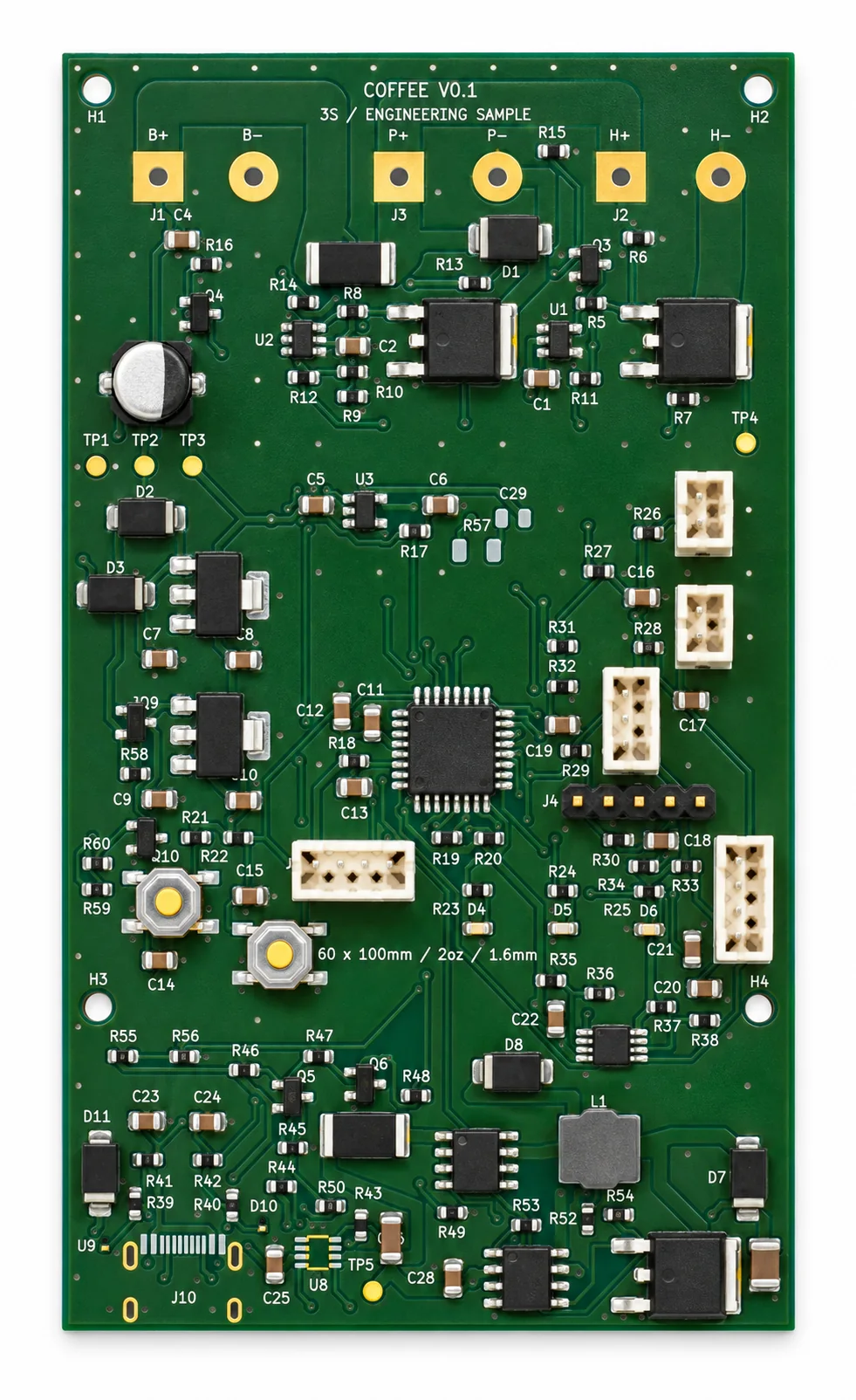
The 60 × 100mm, two-layer layout uses 2oz finished copper. Heater and battery paths are kept wide, while pressure, thermistor, USB-C detect and shunt-sense routes connect to the MCU measurement block. Connector pinouts separate the battery, heater, pump, sensors, display and lid/level contacts.
Heater interface1.8Ω nominal · approximately 88W at 12.6V
Pump interface9.6–12.6V brushed DC · 2A continuous design limit
Sensor interfaces10k NTC · 0–20bar pressure transducer · water level / lid
Component-side design viewCopper-routing side design view
03 / Schematic and PCB details
Trace the power path, sensing and board copper.
A functional overview and native schematic excerpts show how charging, heater and pump switching, sensor feedback and independent protection boundaries fit together. Open any drawing at full size to inspect component references and net labels.
HEATER · POWER BUDGET
Thermal load and current corner
The heater interface is 1.8Ω ±5% with a 70W average-power control target. At 12.6V and the 1.71Ω low-resistance corner, the direct-on calculation is about 7.37A / 92.8W before control and losses; this is a component-sizing bound, not a measured operating result.
USB-C · CHARGER
5V input, 3S charge target
CC detection gates charging to a 5V Type-C source advertising 3A. TPS2557 limits the USB branch and CN3303 provides a 12.6V boost-charge target. USB Power Delivery and higher-voltage input are outside this design interface.
PUMP · PRESSURE LOOP
Separate drive and feedback
The pump connector targets a 9.6–12.6V brushed motor at up to 2A continuous and 4A stall. A 0.5–4.5V ratiometric transducer maps to a 0–20bar input range; heater and pump drive are mutually exclusive.
PROTECTION · CONTROL
Independent hardware boundaries
The external battery pack supplies its own BMS and a 10A fuse at battery positive. The heater path adds a series normally-closed thermostat and one-shot thermal cutoff; USB insertion inhibits the power-drive inputs in hardware, and pressure relief remains mechanical.
Schematic sheets
The four excerpts are rendered from the KiCad source: MOSFET drive and current sensing, MCU and interfaces, temperature / pressure sensing, and the Type-C 3S charger.
01 · Power drivers and current sensingOpen full-size schematic sheet02 · MCU, logic rails and user interfaceOpen full-size schematic sheet03 · Sensors and charge-temperature cutoffOpen full-size schematic sheet04 · USB-C input and 3S boost chargerOpen full-size schematic sheet
Copper routing by layer
Separate KiCad copper plots reveal the actual F.Cu and B.Cu artwork. The 60 × 100mm, two-layer board calls for 2oz finished copper and a 3.5mm primary heater run; the stated minimum track / clearance / drill rules are 0.20mm / 0.15mm / 0.30mm.
F.Cu · Front copper plotOpen full-size copper-layer viewB.Cu · Back copper plotOpen full-size copper-layer view
Values on this page are design inputs, calculated corners or interface targets. Battery charge termination, current calibration, thermal margins, selected pump / heater hardware, hydraulic relief and enclosure fit must be confirmed with the final components and prototype conditions.
04 / Product context
Portable coffee, with heat and pressure in the loop.
A battery-powered espresso appliance compresses several design constraints into a handheld product: rapid thermal energy delivery, controlled pump operation, safe charging and compact sensor wiring. This architecture connects the product brief to concrete board-level interfaces.
Share your heater resistance, battery configuration, pump curve, pressure sensor, enclosure envelope and target test plan to discuss component sourcing, PCBA build and the next design review.