Connect occupied-space CO₂ demand to two EC fans. Sensor acquisition, adjustable voltage mapping, local operation and isolated Modbus integration form one ventilation-control architecture for equipment manufacturers and building integrators.
CO₂ demand changes as people enter and leave. Use a representative occupied-zone sensor to adjust the shared EC fan command, retain a configured minimum ventilation level, and let the building controller supervise operating hours. Set the demand curve from room use, outdoor-air requirements and measured airflow.
Classrooms and training spaces
Class periods create repeatable occupancy changes. A gradual output ramp reduces abrupt fan changes; an expiring manual override supports short-term ventilation adjustments. Commission the minimum and maximum settings against airflow and acoustic measurements for the room.
Hotels, apartments and residential ERVs
Supply and extract fans can share one ventilation demand while using separate voltage ranges and calibration coefficients. Coordinate with the unit’s own frost, bypass and heat-recovery controls. Temperature and humidity measurements are available for supervision; this controller’s automatic demand is based on CO₂.
Equipment manufacturers
Use the controller architecture alongside EC fans, an ERV/HRV or a ventilation cabinet. Specify fan input impedance, analogue common, enable-contact electrical limits and healthy-contact behavior in the equipment interface sheet. Match terminal layout, display location and sensor exposure to the enclosure.
Building integration and refurbishment
A PLC or BMS acts as the Modbus RTU master and reads measurements, active state and faults. Retrofit is suitable where the fan already accepts compatible voltage and dry-contact controls. Units with PWM, proprietary bus or powered fault outputs require an explicit interface adaptation.
Multi-zone buildings
Assign a unique bus address to each controller and plan a representative measurement point for each ventilation zone. One local CO₂ measurement cannot describe every room in a large floor. Higher-level scheduling and cross-zone coordination belong in the BMS.
CO₂, temperature and humidity sensing
Sensor architecture
Sensirion SCD41 supplies CO₂ readings and SHT41 supplies temperature/humidity over I²C to STM32G0B1CBT6. Drivers check communication and data validity. Status distinguishes the last reading from its freshness so that a stale value does not silently remain a valid control input.
Representative air exposure
Keep the sensing path open to the occupied zone and separate it from power-conversion heat, direct supply jets, sunlight and exhaled breath. Choose room sensing or return-air sensing deliberately; each observes a different air mixture. Enclosure airflow and board heating influence the complete measurement chain.
What the measurements mean
CO₂ is used as a ventilation-demand input associated with occupancy. It does not measure particles, VOCs or carbon monoxide. Temperature and humidity are displayed and exposed to the master; they do not independently start or stop fans in this control profile.
Pressure and baseline management
The configuration accepts ambient pressure from 700 to 1200 hPa; use the relevant site pressure rather than treating the default 1013 hPa as a measurement. Automatic self-calibration is off by default and is checked after sensor startup. Select ASC according to whether the site regularly reaches a suitable reference-air baseline.
Ventilation demand and control priority
Configurable CO₂ curve
The example profile uses 800 ppm as the lower point and 1400 ppm as the upper point. Below the lower point it requests minimum ventilation; above the upper point it requests maximum; between them it interpolates from filtered CO₂. These are adjustable control examples, not universal air-quality limits.
Shared demand, separate output mapping
Both fan channels follow the same demand percentage. Each channel has its own minimum/maximum voltage and gain/offset coefficients, allowing different fan response ranges. There is no pressure sensor, airflow feedback or independent supply/extract closed loop in this architecture.
Warm-up, ramp and temporary override
Automatic control waits at least 180 seconds and three consecutive valid CO₂ samples at startup. The profile limits demand changes to about two percentage points per second. A manual command has a 1–900 second lease, default 60 seconds, then returns to automatic control.
Priority and stale-sensor behavior
Maintenance mode, installation authorization, RUN permission and enabled fan-health faults take priority over manual demand. CO₂ with no new valid sample for more than 30 seconds invokes the configured fallback demand and marks the reading stale. A DAC communication or readback fault disables relay outputs.
Use the expression only between the two CO₂ points; outside them, clamp to the configured minimum or maximum. The demand variable is a command percentage, not measured airflow. Per-channel voltage mapping follows the configured demand and endpoints.
EC fan controls and dry-contact inputs
Two voltage outputs
DAC80502 produces two analogue setpoints, amplified by OPA2197 for 0–10 V control. Connect each output to a fan’s voltage-control input and analogue common, with input impedance of at least 10 kΩ. The fan uses its own motor power supply; these outputs carry control signals.
Enable contacts and stop state
A DPDT relay per channel combines a dry-contact enable path with analogue-output switching. The de-energized state opens enable and connects the analogue output to logic ground. For equipment matching, use the project interface envelope of 30 VDC / 50 mA for enable contacts and check the fan’s switching specification.
RUN and maintenance control
The RUN dry contact permits relay drive when closed; opening it disables drive through the hardware gate. The maintenance jumper permits configuration writes while keeping outputs disabled. The installer confirms the equipment profile locally before enabling normal operation.
Fan health and compatibility
Optional feedback expects a contact closed in the healthy state. An enabled health fault latches and requires healthy restoration plus local acknowledgement. Identify healthy contacts, fault-only contacts and tachometer pulses separately; do not connect powered outputs to the logic dry-contact inputs.
Connector
Signal
Wiring role
J1.1 / J1.2
DC+ / GND
18–30 V DC
J4.1 / .2 / .3
D1+ / D0− / GNDS
Isolated RS485 common
J6 / J7
AO1 / AO2 + GND
Voltage-control input; ≥10 kΩ
J8 / J9
ENABLE1 / ENABLE2
Dry contacts; 30 VDC / 50 mA project envelope
J10
RUN
Passive closed contact permits operation
J11 / J12
HEALTH1 / HEALTH2
Optional passive healthy-closed inputs
J3
MAINTENANCE
Configuration access with outputs disabled
Isolated RS485 and building-system integration
Electrical bus architecture
ISO1410 and an isolated RECOM R05CT05S power path separate the RS485 common from the controller logic ground. J4 provides D1+, D0− and GNDS. Use a trunk with short stubs, a compatible common conductor and a defined shield strategy; avoid reconnecting GNDS to the controller power negative.
Addressing and line format
The controller is a Modbus RTU slave. Defaults are address 1, 19200 baud and 8E1; configuration supports addresses 1–247, 9600/19200/38400 baud and 8E1 or 8N2. Verify D1/D0 polarity from the adapter manual rather than assuming A/B labels have a universal meaning.
Registers and parameter commit
Input registers expose readings, demand, state and health. Holding registers stage parameters in RAM; a separate commit applies a validated complete configuration to nonvolatile storage. PDU addresses are zero-based. After address or format changes, reconnect with the new communication settings and read back active configuration.
Termination and system access
Enable the board’s 120 Ω termination only at a physical bus end. Account for termination already present in the master or adapter. Modbus RTU provides neither user authentication nor encryption; keep the field bus inside a tracked network and put remote access authorization at the BMS gateway.
Power, PCB and local operation
18–30 V DC input
The input path combines a fuse, TVS and TPS26600 protection for reverse polarity, overcurrent and voltage conditions. Local rails supply 5 V, 12 V and 3.3 V functions; isolated 3.3 V supplies the bus side. Use a suitable DC supply and route fan motor power separately from controller signal power.
Four-layer mixed-signal layout
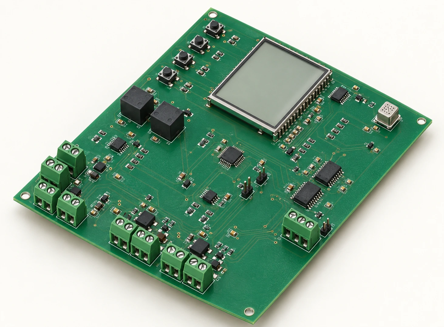
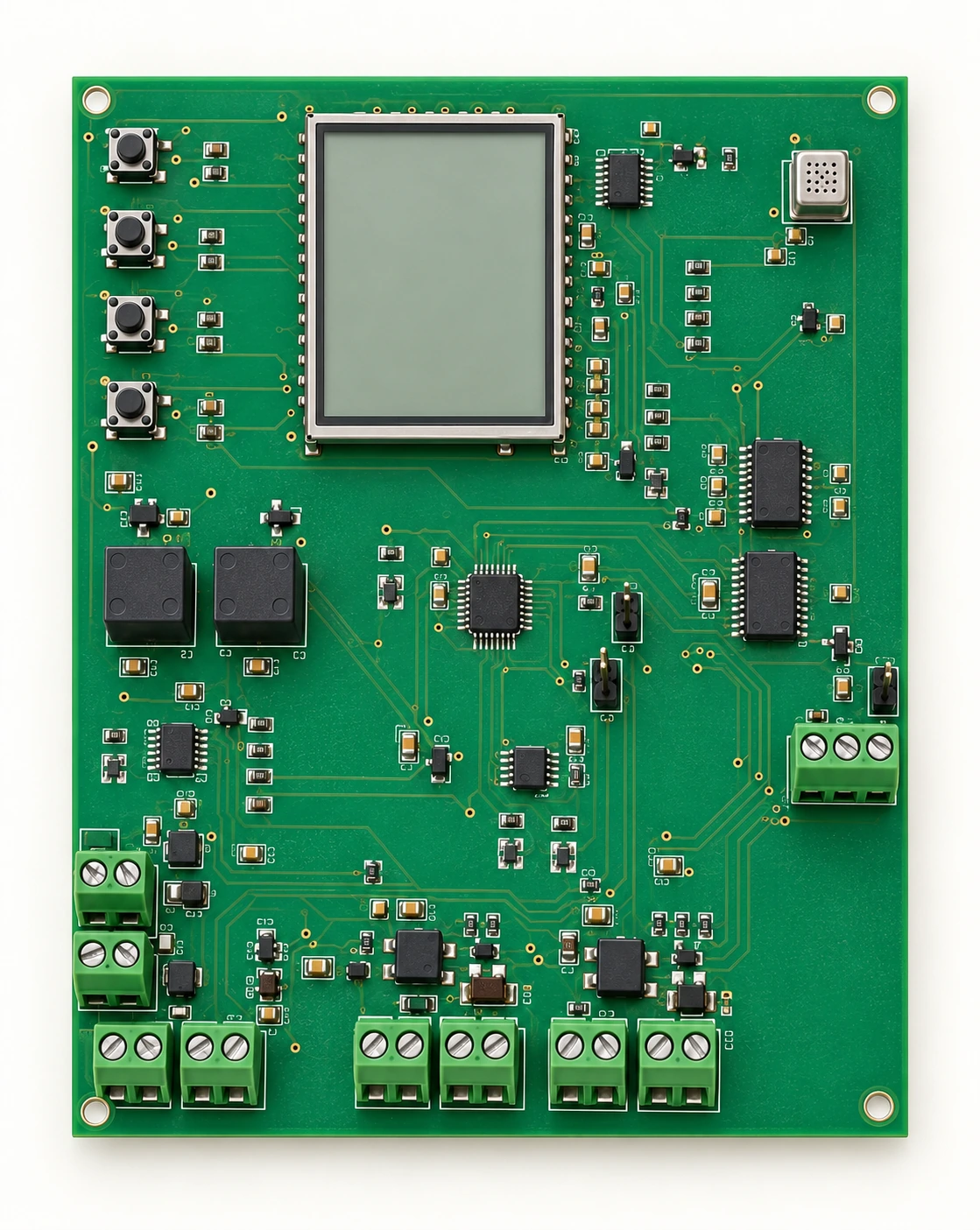
The 140 × 178 mm PCB architecture separates input protection, conversion, sensing, analogue outputs and isolated communication. Local decoupling and short reference paths support sensor and DAC circuits. Isolation keepouts, return paths, connector placement and service access are part of the board-to-enclosure interface.
Display and buttons
An EA DOGM128W-6 graphic LCD and local buttons provide measurement, operating-state and service interaction. A dedicated LCD supply and signal-level buffers separate display requirements from MCU logic. Reset, initialization and clearing precede normal display output.
Persistent configuration and recovery
Configuration uses two Flash pages with a commit marker and versioned records. The watchdog supervises firmware execution. CO₂ calibration transactions also retain a pending record so that interruption produces an explicit uncertain maintenance state instead of automatically repeating a calibration command.
Design visualization · sensor, display, power and terminals
SCD41 + SHT41I²C → STM32G0B1
STM32G0B1Control · LCD · Flash
DAC80502 + OPA2197AO1 / AO2 → EC fans
ISO1410 + R05CT05SRS485 → PLC / BMS
Installation and commissioning workflow
Survey the ventilation equipment
Record fan models, signal diagrams, input impedance, enable behavior, supply/extract arrangement and required outdoor airflow. Choose representative air exposure and keep sensor openings away from electronics heat. Plan cable separation, service access and the RS485 trunk before selecting the enclosure.
Wire with outputs inhibited
Keep RUN open during wiring. Check J1 DC polarity, J4 isolated common and each AO/enable pair against connector pin 1 markings. Connect only passive contacts to RUN/HEALTH. Do not confuse the fan’s auxiliary 10 V supply terminal with its voltage-control input.
Configure and characterize both fans
Set bus address, demand thresholds, minimum ventilation, fallback demand and the two voltage ranges. Measure start voltage, minimum continuous operation, 0 V behavior and open-input behavior for each fan. Compare supply/extract airflow at several commands, then confirm the equipment profile locally.
Exercise operating transitions
Check automatic demand, temporary override expiry, RUN opening, sensor freshness and healthy-contact faults. Confirm configuration after power cycling and compare readings with reference instruments. Hand over labelled wiring, the active parameter set and measurement records so maintenance can reproduce the installation.
Survey equipment
Wire with outputs off
Configure bus & demand
Match voltage & fans
Exercise transitions
Record & hand over
Calibration and service traceability
CO₂ forced recalibration
Use a traceable CO₂ reference or standard gas in a stable, homogeneous environment. Follow SCD4x assembly-age and conditioning requirements: at least five days after assembly and at least three minutes of periodic operation in the reference environment. The service workflow accepts a 400–2000 ppm reference and uses local confirmation.
One calibration request, explicit recovery
Each request uses a fresh nonce and a receipt file. Before issue, firmware journals the transaction; it stops measurement, observes the sensor timing and checks the returned result and CRC. A timeout or uncertain result is investigated through status readback rather than an automatic write retry.
Independent analogue gain and offset
Measure at least three settled voltage points spanning at least 5 V, for example around 2/6/10 V, with a suitable high-impedance meter. Fit gain and offset separately per channel, accounting for the current coefficients and DAC quantization. Commit changes in maintenance mode, then remeasure zero, intermediate and endpoint outputs.
Measurement records for service
The macOS/Linux serial tool supports status, configuration staging/commit, expiring override and CSV logging. Retain equipment identity, firmware identity, instrument calibration, actual pressure, CO₂ reference, voltage measurements and final configuration. DAC register readback describes the command; a meter describes terminal voltage, and an airflow instrument describes ventilation.
A wall-mounted controller architecture for offices, meeting rooms, schools and building integration: warm-white surfaces, a portrait display, four local keys, a removable wall bracket and concealed wiring.
Appearance & local operation
Overall dimensions are 176 × 224 × 40 mm including the bracket, with keys protruding another 0.1 mm. The RAL 9002 warm-white finish, black display window and four-key layout are documented with gloss, seam and lens-flush targets. Portrait firmware covers display orientation and operation screens.
Assembly & service
The enclosure follows the 140 × 178 mm PCBA layout. Shells, lens, key caps, POM guides, silicone tips and springs have separate models. A 6061 aluminum bracket provides downward hanging and a bottom lock; three DXF layouts locate the front, rear and bracket features.
Sensors & wiring
Air openings, sensor space and wire routing coordinate CO₂/temperature/humidity sensing with the control electronics. The accessory list identifies Belden 9842 communication cable, terminals, strain relief and an external 24 V supply. Fan mains wiring is separated from control signals.
Equipment integration
The supply reference is GST25B24-P1J and the EC fan interface reference is K3G190-RC05-03. Equipment profiles account for input impedance, starting voltage, feedback semantics and the required airflow/static pressure. USB-RS485 and STLINK tools support configuration, programming and debugging.
The complete archive contains 69 CAD items, assembly/exploded STEP, individual STEP/STL, three DXF layouts, modeling parameters and scripts, a 33-item accessory list, portrait firmware sources and BIN/HEX/ELF/MAP images. Materials, dimensions, finish targets and inspection methods are documented in the design book and editable files.
Technical resources
Download the application and engineering descriptions or the register map for system integration.
Download the complete package or select electrical drawings, native PCB sources, BOM, CAM, firmware, serial tools and mechanical installation files. The full package also includes assembly STEP, portable 3D models, commissioning/calibration documents and integrity manifests.
The outputs share one CO₂ demand and use separate voltage ranges/calibration. Airflow and pressure loops need corresponding sensors and another control specification.
Does a 50% command mean 50% airflow?
No. Voltage, motor speed and delivered airflow depend on fan electronics and duct resistance. Build an equipment-specific mapping using actual airflow measurements.
Can it connect to BACnet?
The field interface is Modbus RTU. A BMS gateway can translate the defined registers to another protocol; this requires gateway mapping and system integration.
Can humidity control a humidifier or dehumidifier?
Humidity is monitored and reported. Humidifier/dehumidifier control needs a specified output, interlocks and a corresponding firmware profile.
Which details define fan compatibility?
Provide voltage-input impedance and common, starting/stop behavior, enable circuit limits and healthy-contact logic. RPM pulses, PWM and proprietary buses require explicit adaptation.
Configure the controller around your equipment
Share fan models and interface diagrams, supply/extract arrangement, room use, ventilation targets, BMS protocol, installation environment, enclosure requirements and expected quantity. These inputs define the electronics, wiring, control profile and commissioning workflow.