CNC and legacy-equipment retrofit
Read existing run and alarm outputs without replacing the machine controller. Define overlapping states and validate output loading with the actual machine.
INDUSTRIAL IOT · MSC EVT1
Turn existing machine signals into useful production records. Explore a 24 V collector design with isolated inputs, local pulse counting and secure network delivery — with the engineering files available to inspect.
Fabrication and mass production remain on HOLD. No physical sample or machine-site validation is recorded.
HW EVT1 · FW 1.1.0 · 2026-10-03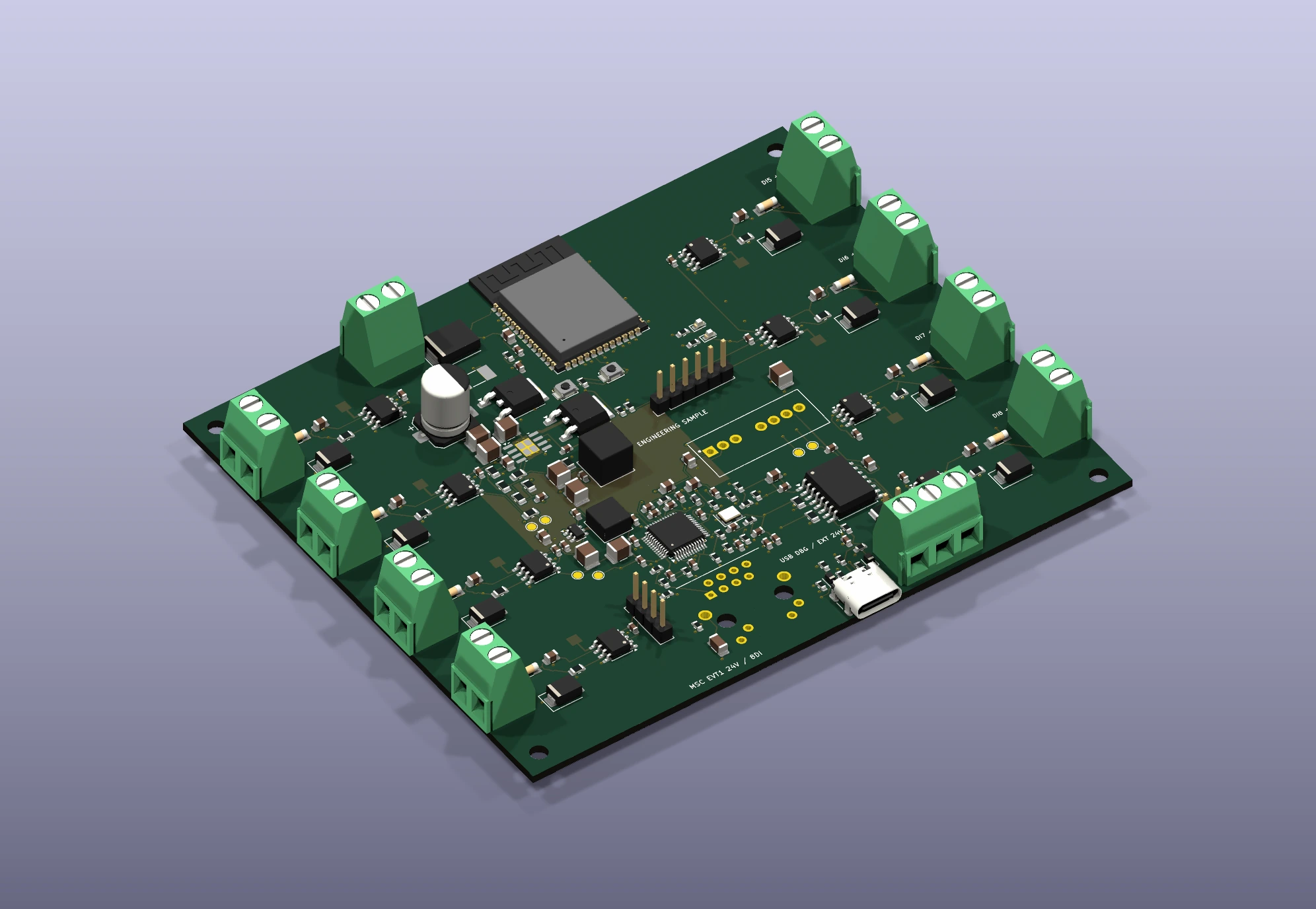
01
A run output, alarm relay and cycle pulse carry different meanings. Define the source, voltage, polarity, return and event meaning before designing a dashboard. This collector monitors low-voltage signals; the machine retains its own control and interlocks.
Read existing run and alarm outputs without replacing the machine controller. Define overlapping states and validate output loading with the actual machine.
Count a verified cycle-complete pulse locally on DI3/DI4. A cycle pulse is not automatically a good-part count; quality needs its own trusted signal or production data.
Normalize signals from several machine types into a common event model for a dashboard or MES. Machine mapping, job context and backend integration are project-specific.
Application examples for project planning. No completed customer installation, OEE improvement or field reliability result is claimed.
02
Isolation is functional: each DI has its own return, and RS485 SG is separated from MCU DGND. Main supply 0 V and DGND are connected. This assembled design has no safety-insulation certification. USB needs external 24 V; there is no USB power or PoE. The 0–50 °C dry-cabinet environment is a design target.
| PNP / PLC 24 V | Output → DI+; source 0 V → that DI−. |
|---|---|
| Dry contact | Signal +24 V → contact → DI+; signal supply 0 V → DI−. |
| NPN open collector | Signal +24 V → DI+; sinking output → DI−. Check leakage and off-state voltage. |
| RS485 | J13: A/D+, B/D−, SG. Daisy-chain; two end terminations. J14 enables the existing 120 Ω resistor. |
J12: +24 V / 0 V. J4–J11: DI+ / DI−. Keep PE/shield, RS485 SG and DGND distinct. Check the schematic and peer manual before wiring. No direct mains, VFD motor outputs, CT, vibration, 4–20 mA or 0–10 V input is provided. External bus TVS is not populated; RS485 surge/EFT and 24 V miswire immunity remain unverified.
03
Six status channels use 5 ms sampling and 30 ms debounce. DI3/DI4 count pulses locally. Normal snapshots are every 10 s; status-triggered records are limited to one per 2 s. Counters are 64-bit decimal strings.
MQTT over TLS checks the certificate and hostname; SNTP is required. QoS 1 is paired with an application ACK. The included SQLite receiver commits the transaction before acknowledging the record.
The NVS queue holds 256 records: about 42 min 40 s at 10 s, or 8 min 32 s at a continuous 2 s rate. When full, it keeps older records, drops new records and counts the drops. Counter checkpoints are every 30 s; sudden power loss can lose counts since the last checkpoint.
Queue capacities are arithmetic, not tested endurance. Random power cuts, flash wear and reconnect behavior still need sample tests. USB provisioning selects Wi-Fi or Ethernet, not both. Open Wi-Fi, enterprise 802.1X, AP provisioning, FRAM/hold-up and OTA are not included. The receiver is a backend reference, not a deployed cloud service.
04
The 21-item standard accessory list covers power, signal cables, ferrules, enclosure, mounting and cable entry. It assumes an existing accepted cabinet AC branch, PE arrangement and mounting wall; installation labor and distribution changes are outside this budget.
Mean Well HDR-30-24; LAPP 10035040 power cable, 0035812 DI cable and 2170204 RS485 cable. Default lengths: 2 m power, two 5 m DI runs and 5 m RS485.
Hammond 1554W2GY + 1554FT; custom unclad FR4 adapter MSC-MNT01-REV-A; M3 nylon spacers, enclosure screws and separate cabinet-wall fasteners.
LAPP 53111020/53119020, icotek 45024/51380, Phoenix ferrules and 1019440 shield clamps. Qualify cable diameter, connector passage, terminal grip and strain relief on samples.
Pepperl+Fuchs NBB4-12GM50-E2-V1-M, V1-G-5M-PUR-ABG cable and BF12 bracket, with ferrules and M16 entry hardware. Six extra line items; one PNP NO channel. Target material and mounting distance must be confirmed.
Keep the onboard antenna's front 15 mm clear of metal and large harnesses. Check Wi-Fi with the cabinet closed; Ethernet may suit a screened cabinet. Modified-enclosure IP performance is untested. The optional proximity sensor supports metal targets; other targets need a different qualified sensor.
05
Engineering USD references dated 2026-10-03, not supplier-confirmed commercial quotations. Freight, tax, NRE, certification, installation and margin excluded.
| PCBA · 100-unit scenario | $76.39–84.39 |
|---|---|
| PCBA · 1,000-unit scenario | $63.82–69.32 |
| 21-item standard accessories | $132.04–249.16 |
| PCBA + accessories · 1,000-unit scenario | $195.86–318.48 |
| Optional one-channel sensor kit · extra | $81.89–147.14 |
Reuse a qualified 24 V supply or a shared USB service station where the site allows it. A Wi-Fi installation can omit the external Ethernet cable and split entry; the PCB's Ethernet parts are still populated. Future Ethernet DNP, second-source DC/DC and terminal substitutions need separate validation before any savings can be promised.
Review power loops, USB/Ethernet return paths and impedance, fabricator stack-up, exact footprints and connector sample fit before fabrication.
Measure supply behavior, DI thresholds/counting, RS485, TLS recovery, random power loss, heat, RF/EMC and enclosure/harness fit.
Establish environmental, endurance and system-recovery limits for the chosen machine, enclosure and installation.
Qualify the fixture, cycle time, first-pass yield, rework process, firmware identity and unit traceability. These runs have not occurred.
Recorded software evidence: ERC 0; DRC violations, unconnected nets and schematic-parity issues 0 under the supplied rules; 166 BOM/placement positions and 513 pin/net bindings checked; target build and host tests pass. Ignored checks remain in the reports. Fifteen EVT plan items are NOT_RUN. The USB tool checks a snapshot only; it does not operate a full FCT fixture.
06 · EVT1 / 20261004
Free direct downloads, no form required. Complete source, binaries, drawings, selected accessories, budget, mechanical files, HOLD CAM data and test evidence are included. Design documents are mainly Chinese; the added application/integration guide is English. All archives remain engineering-review material.
SHA-256 04c92d1cf6958531b400bba00c7b72841b3ec435bab3fe7142f5a356b8b0a6f1SHA-256 382319279676c4cf407ef130f155501b17db58750c4c00bf62b58340dc189866SHA-256 f6bcd60a9ca06e637d3c8a67a5cb1c97c1aed010404bf690f0b9f855f32219ccSHA-256 00165e2c0f2f44573a97002e420174b51aa2c562861a3c45f561329f9c5913e5SHA-256 46c80d90effcebbd09e4a9c6e17114b12d733c3098daf0a62e3aea81ac778adaSHA-256 f57990cef58edf4537913f5680fd344e6581ca8996fad92ef7e6ab2bd76df49dSHA-256 f16bccbbd7c9fe48a01a61628d0e8847742c9f809b3aab5324f18f8ec64acf89SHA-256 6107e682ccb155b61c923db2f3dd8645ae46d7d67e1e64be4e349caa8b8f90a9SHA-256 13dde22372b752abcdffd4f85f88cbef25860f43b52dcbd327304d281a35de47SHA-256 7d05fd857dbc7b50a84aa537de89900855da30f51bf952babb861776c4df21e7SHA-256 863fdca070ba1e3b26b10a9dcd7aee0127ff4c53bd38bdf53fd28cfc6ec21e7fPublic edition: 2026-10-04. Personal build paths are anonymized; the diagnostic ELF is stripped of debug sections. Flashable BIN images are unchanged. Third-party notices and regenerated public checksums are included. Original diagnostic reports remain historical evidence; use the public manifest to verify this download.
Use verified 24 V digital sources with a defined return and input-loading budget. Analog, vibration, CT and mains signals need a separately designed and validated front end. A metal proximity sensor is one optional choice, not a universal sensor.
The ≤1 kHz target has not been accepted on hardware. Counts are checkpointed every 30 s and the offline queue is finite. Specify acceptable outage duration and count-loss limits; lossless requirements may need a different storage/power design.
The files are an engineering review candidate on fabrication and mass-production HOLD. An inquiry can define adaptation, DFM closure, validation samples and release criteria. A released production quotation follows the agreed files, quantities and test scope.
A cabinet can screen the onboard antenna. Survey the actual installation and test with doors closed. Ethernet is populated as an alternative; a different external-antenna module would require an architecture and qualification change.
MSC EVT1
Share the machine type and signal drawing, voltage/polarity/frequency, cabinet and network conditions, required outage/count-loss window, backend or MES interface, pilot/annual quantity, installed-cost target and date. We can then define electronics, firmware, accessories, validation and assembly scope.
Use the existing NDA process before sharing confidential machine files.
These sources describe components and tools; their ratings do not certify this assembled design. Exact accessory sources remain in the downloadable CSVs.