Packaging & assembly machines
View production counts, running states and fault codes from the PLC. A diagnostics page separates communication timeouts and exception responses from equipment data, giving operators a single panel for the machine.
INDUSTRIAL HMI · HMI700
Bring equipment data, parameter viewing and service diagnostics onto one capacitive touchscreen. HMI700 connects to a PLC or controller through isolated RS485, receives classic CAN diagnostics, and integrates display, power, touch and local settings storage on a 160 × 100 mm board.
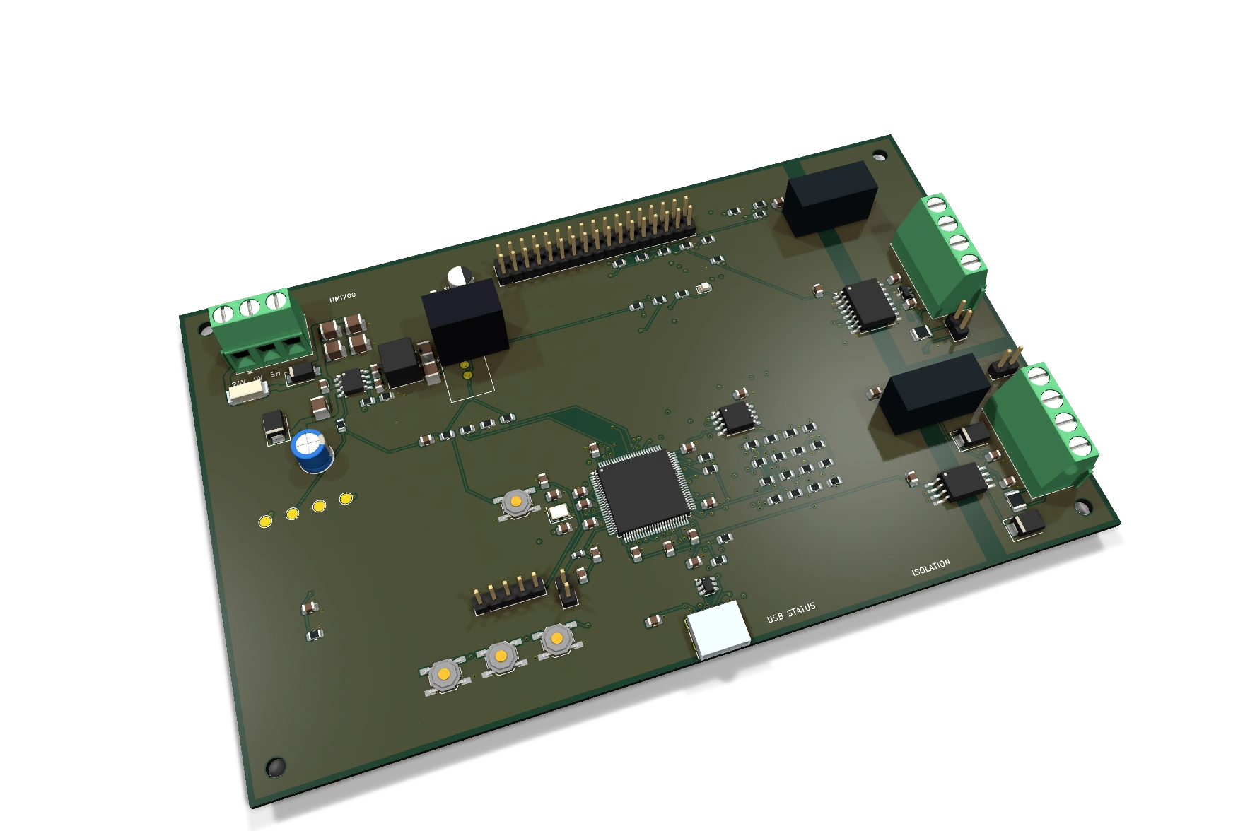
A local operator interface for indoor equipment panels and control cabinets. The HMI reads controller data; equipment interlocks and actuation belong to the PLC, dedicated controller and safety circuits. Units, ranges, alarm wording and register addresses are mapped to the equipment protocol.
View production counts, running states and fault codes from the PLC. A diagnostics page separates communication timeouts and exception responses from equipment data, giving operators a single panel for the machine.
Display controller-supplied temperature, level, pressure and flow registers, with a visible distinction between current values and stale data. Sensor acquisition, PID, contactors and independent thermal protection remain in the equipment controller.
Present pump states, totalized flow, operating hours and fault information. Use RS485 for the field controller and map parameter names, engineering units and permitted commands to its register table.
Organize counts, step codes and result codes into local pages. Back, confirm and next-page buttons support menu navigation; USB status queries provide a diagnostic connection to the workstation.
Add local visualization to an existing 24V cabinet while retaining the PLC control architecture. Adapt the RS485 address, baud rate, panel cutout and harness length to the installation.
Receive classic CAN status frames and show reception counters and communication errors. The included receive setup uses 500kbit/s and standard ID 0x180; field decoding can be adapted to the equipment protocol.
The display module handles frame storage and graphics output. The main board handles page logic, data parsing and power. Each field communication interface has its own isolated supply; the display and MCU share the logic domain.
Fuse / reverse-polarity diode / TVS
LMR36520 / TSR 2-2433
Pages / communication / watchdog
RA8875 display / GT911 touch
Isolated RS485 / isolated CAN
USB CDC / SWD / SPI Flash
24V → 5V → 3.3V → MCU / LCD · MCU ↔ RS485 / CAN · MCU ↔ USB / SPI Flash
| Module | Selection | Design detail |
|---|---|---|
| MCU | STM32F407VGT6 | 168MHz Cortex-M4; FSMC drives the 16-bit display bus, I²C reads touch and SPI connects settings storage. |
| Display & touch | Waveshare 7inch Capacitive Touch LCD (C), GT911 | 800×480; RA8875 display controller and frame storage; 34-pin 2×17 host connection. |
| 24V input & 5V | LMR36520ADDAR + XAL6060-153MEC | 18–30V design input range; 15µH inductor and ≤1.7A continuous 5V design budget. Fuse, series diode and TVS form the input protection path. |
| Input capacitance | 5×2.2µF/100V X7R + 220nF/100V | 11µF nominal; effective capacitance is evaluated for 30V DC bias, tolerance, temperature and aging. The local smaller capacitor provides high-frequency bypass. |
| 3.3V branch | TRACO TSR 2-2433 | Converts 5V for the MCU and display; ≤1.4A continuous system design budget, allocated using full-brightness and startup demand. |
| Isolated RS485 | TI ISO1410DWR + TRACO TMR 1-0511 | Separate logic and bus-side grounds; SM712 at A/B, with 100nF and 10µF local decoupling. JP2 inserts a 120Ω termination. |
| Isolated CAN | TI ISO1042DWVR + a separate TMR 1-0511 | Classic CAN 2.0; CAN_H/CAN_L TVS protection and JP3 120Ω termination. Its bus-side supply is independent of RS485. |
| Settings storage | Winbond W25Q64JVSSIQ | 8MB SPI Flash; two independent 4KiB sectors alternate local settings records with CRC32, sequence numbers and a commit marker. |
| USB service | USB-C / USB 2.0 Full Speed / USBLC6-2SC6 | Self-powered CDC device; VBUS sensing is separate from board 5V. D+/D− have ESD and series damping; STATUS returns diagnostics. |
| PCB & assembly | 160×100mm / 4 layers / 115 parts | 103 SMT plus 12 through-hole components; two optional bias resistors are unpopulated. Four M3 hole centers: (5,5), (155,5), (5,95), (155,95)mm. |
| Port | Pinout | Connection |
|---|---|---|
| J1 · power | 1=+24V; 2=GND; 3=CHASSIS | Nominal 24V DC; CHASSIS is the functional shield reference. |
| J2 · display | 34 pins, 2×17, 2.54mm, straight-through | 3.3V; D0..D15, CS, RS, WR, RD, RESET, WAIT and touch INT/SDA/SCL. |
| J5 · RS485 | 1=A; 2=B; 3=ISO485_GND; 4=CHASSIS | A is non-inverting. Some controllers reverse A/B naming; verify polarity. |
| J6 · CAN | 1=CAN_H; 2=CAN_L; 3=ISO_CAN_GND; 4=CHASSIS | Terminate the two bus ends; do not add termination at every node. |
| J4 · SWD | 1=VTref; 2=SWDIO; 3=SWCLK; 4=GND; 5=NRST | VTref senses board 3.3V; avoid competing debugger and board supplies. |
| J3 · USB-C | USB 2.0 FS self-powered device | Connect a data cable to the PC. Equipment power comes from the 24V input. |
J2 pins 3..18 carry D0..D15; 19..23 are CS/RS/WR/RD/RESET; 25 and 33 are 3.3V; 2, 26 and 34 are logic ground; 29 is WAIT; 30..32 are touch INT/SDA/SCL. Pin 26 selects 16-bit 8080 mode. Pins 1, 24, 27 and 28 are reserved. The module’s internal 40-pin flex is not the main-board host connection.
The firmware uses STM32Cube and PlatformIO. Status, settings and diagnostics/alarm pages use GT911 single-point interaction and the module’s built-in Western character set. Equipment-specific fonts, units, trends and alarm history can be added for the application.
The application reads the remote device by default. FC06 frame generation and response validation functions are included; device writes require the actual protocol and operator permissions. CANopen, J1939 and CAN FD require separate adaptation. ST-Link/SWD downloads firmware; USB CDC provides status queries.
USB CDC > STATUS
Modbus RTU > FC03 · 8 registers · 115200 / 8N1
CAN > 500 kbit/s · standard ID 0x180
SWD > pio run -t uploadThe system selection separates display, external 24V power, harnesses, installation parts and service tools. Download 23 accessory lines and 17 harness-material lines; the complete package also includes five mechanical DXF/SVG designs.
| Accessory | Selection / type | Integration |
|---|---|---|
| Display module | Waveshare SKU8964, GT911 version | Match the 34-pin direction, full-brightness current and glass support locations. |
| Cabinet supply | Mean Well HDR-30-24 | 24V DIN-rail supply; mains wiring belongs to the cabinet design. |
| Display harness | 34-pin, 1:1 straight-through | Mark pin 1 with the red edge at both ends. Use only 3.3V and keep it short, away from power switching wiring. |
| Field harnesses | RS485 / CAN / shield reference | Keep each isolated ground and shield reference distinct; coordinate shielding with the machine grounding arrangement. |
| Mounting & structure | M3 standoffs, screws, backplate, bezel, clamps and insulating/contact pads | Set the cutout and clamping from glass, visible area, PCB thickness, cable exit and support geometry. |
| Service tools | Genuine ST-LINK/V2, USB data cable and bus adapters | Match VTref, SWD and isolated bus wiring. Shared service tools are separate from per-machine material. |
The display and MCU share logic ground. RS485 and CAN each use their own isolated bus ground; avoid shorting all three domains together. Implement emergency stops, drive permissions and independent protection in the equipment architecture. The touchscreen provides operator interaction and information.
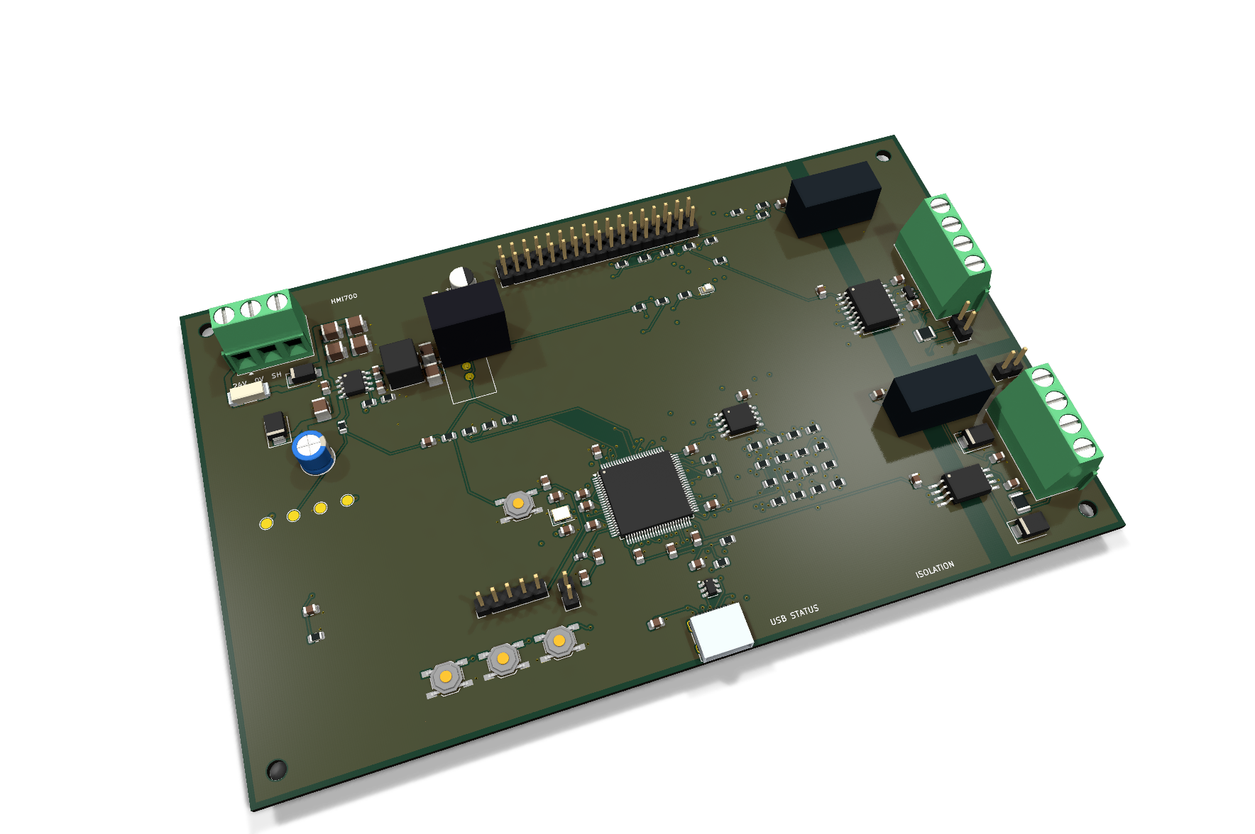
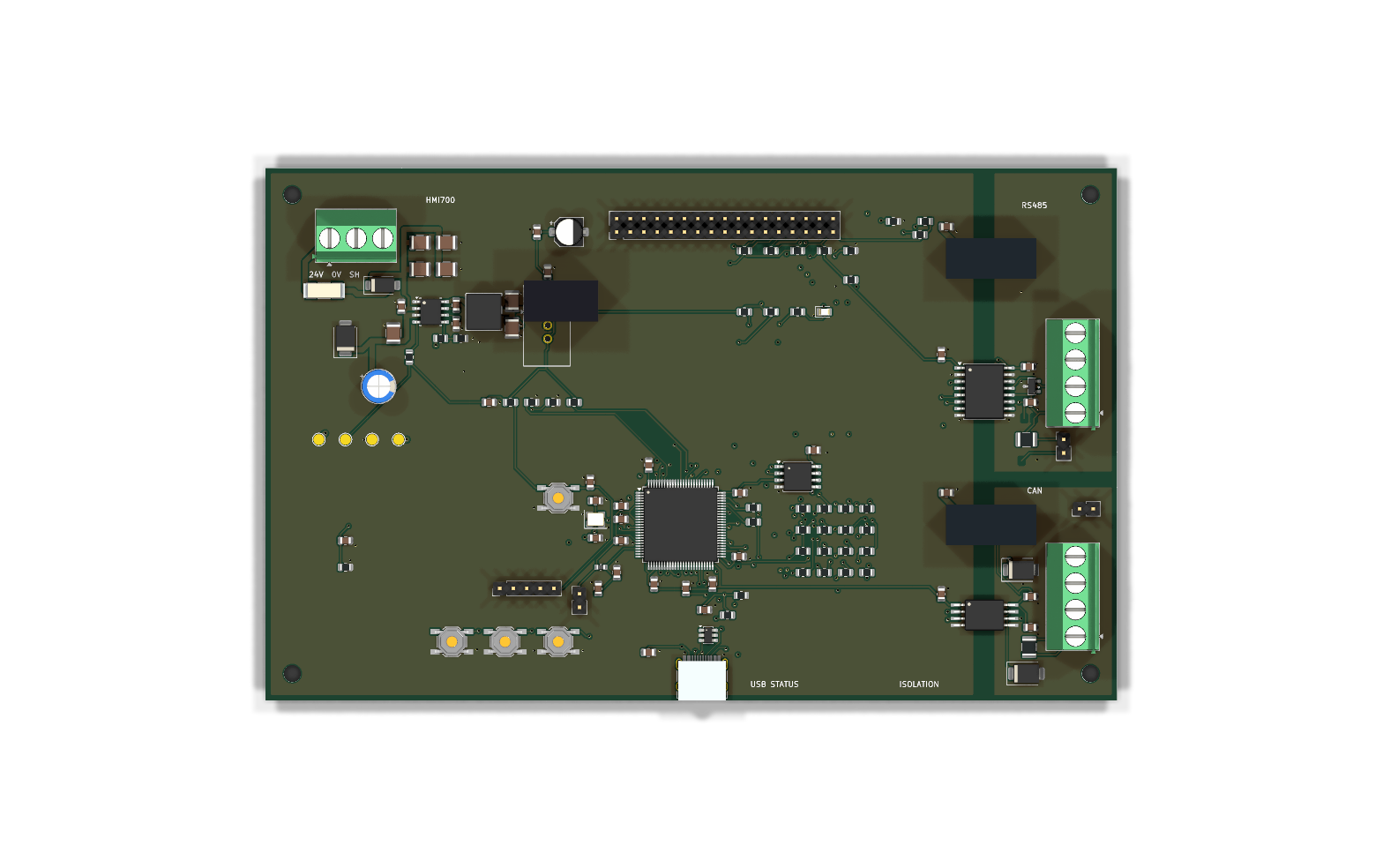
Download without registration. The complete package contains KiCad schematics and PCB, footprint libraries, BOM, Gerber/drill/placement files, firmware source and ELF/BIN, accessories, harnesses, mechanical drawings, integration documents and 3D assets. Category packages support hardware, firmware and mechanical work; original engineering records are retained in the complete archive.
Share the machine type, controller protocol, register map, page requirements, display brightness, board size and panel cutout to define the HMI scope.
Discuss HMI development ↗