Explore 10 reference designs for feeders, litter boxes, trackers, and connected pet products. Compare the electronics, firmware, and tests your project needs before committing to a design.
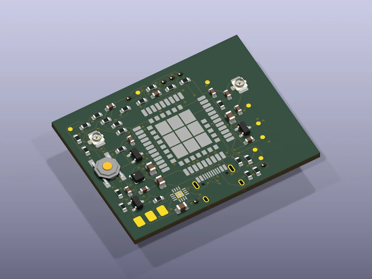
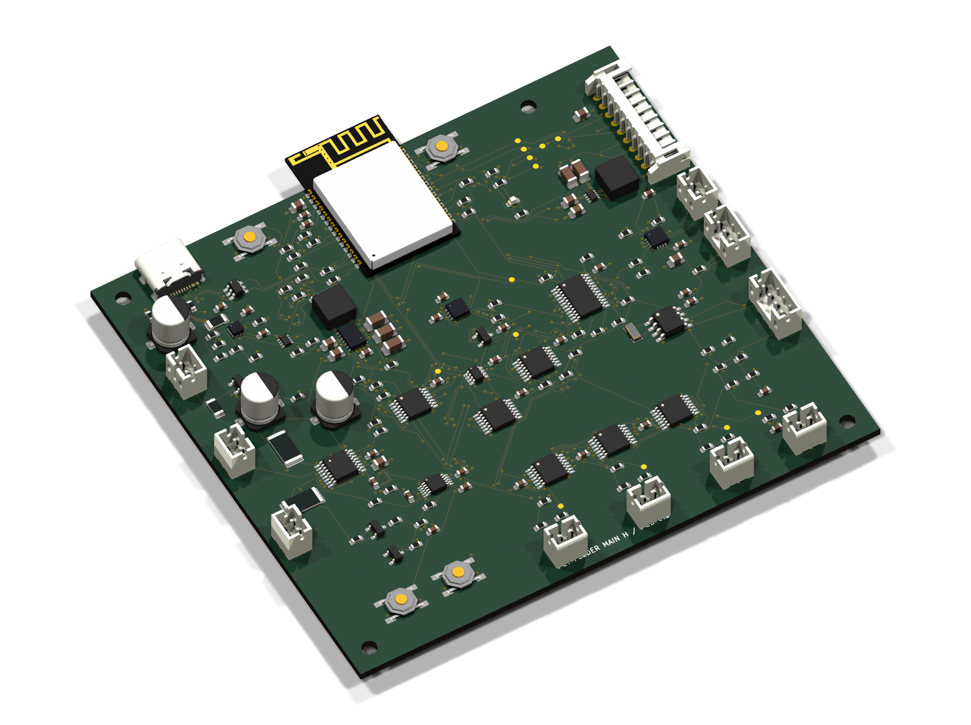
Smart litter-box controller. A board design you can inspect.
Explore the STM32G0 + ESP32-C3 architecture, DRV8876 motor drive, ADS1232 weighing front end and hardware-interlock design. Editable KiCad source, connector definitions and engineering audits are shared under CERN-OHL-P-2.0.
Find your application, compare the main design risk, and open the engineering notes for architecture and validation details.
10 of 10
Representative PCBAPET-01
Visible hardware paired with architecture, risk, and validation evidence.
PET-01 · Feeding & WaterMedium
Feeder Main Control
A representative engineering reference for scheduled dry-food dispensing, portion control, sensing, user-interface communication, and power management.
Architecture
An MCU coordinates a geared dispensing motor, position or blockage sensors, a front-panel interface, local storage, and regulated power rails.
Risk to close
Keep portions repeatable as kibble size and hopper load change.
Validation gate
Run portion-accuracy trials across representative kibble sizes.
DispensingMotor ControlSensors
Representative PCBAPET-02
Visible hardware paired with architecture, risk, and validation evidence.
PET-02 · Feeding & WaterLow
Feeder UI Board
A representative development architecture for a compact feeder user-interface board with manual-feed, reset or pairing input, and multi-state indication.
Architecture
Tactile inputs and LEDs connect through a simple harness or board interface to the appliance main controller.
Risk to close
Maintain clear status meaning with very limited controls.
Validation gate
Verify debounce, long-press, and stuck-key behavior.
HMILEDInterface
Representative PCBAPET-03
Visible hardware paired with architecture, risk, and validation evidence.
PET-03 · Feeding & WaterMedium
Connected Feeder / Waterer
A representative engineering reference for a connected pet appliance combining timed operation, status display, temperature selection, and pump, heater, or feeder interfaces.
Architecture
A central controller links a display and key panel, wireless module, temperature and level sensing, and isolated output stages for pumps, heaters, or motors.
Risk to close
Separate wet-area sensing from mains or higher-current loads.
Validation gate
Test level, dry-run, and temperature-sensor fault handling.
TemperaturePump ControlConnectivity
Representative PCBAPET-04
Visible hardware paired with architecture, risk, and validation evidence.
PET-04 · Feeding & WaterLow–Medium
Pet Appliance Prototype
A representative development architecture for prototyping connected pet feeders or waterers with wireless modules, keys, voice prompts, sensors, pumps, heaters, or motors.
Architecture
A modular MCU baseboard exposes power, wireless, audio, sensor, and actuator interfaces for rapid appliance bring-up and firmware integration.
Risk to close
Keep prototype interfaces flexible without masking electrical limits.
Validation gate
Verify every external interface against its intended load and cable length.
PrototypeWirelessIoT
Representative PCBAPET-05
Visible hardware paired with architecture, risk, and validation evidence.
PET-05 · Litter AutomationMedium–High
Connected Litter Box
A representative engineering reference for motorized litter-box cleaning with wireless reporting, position sensing, and multiple pet-safety inputs.
Architecture
An MCU and wireless module supervise a drum or rake motor, home and travel sensing, presence or weight inputs, current monitoring, and protected power stages.
Risk to close
Prevent motion whenever a pet or obstruction may be present.
Validation gate
Run pet-presence, obstruction, and sensor-disagreement fault injection.
SafetyMotionWireless
Representative PCBAPET-06
Visible hardware paired with architecture, risk, and validation evidence.
PET-06 · Litter AutomationMedium–High
Radar Litter Box Control
A representative development architecture for self-cleaning litter-box motion control with an external radar or presence-sensing interface and multiple mechanism sensors.
Architecture
A main MCU evaluates presence, position, and motor-current signals before enabling a protected drive stage for the cleaning mechanism.
Risk to close
Avoid false-clear decisions from a single presence sensor.
Validation gate
Test detection coverage with representative pet sizes and positions.
RadarMotor ControlSafety
Representative PCBAPET-07
Visible hardware paired with architecture, risk, and validation evidence.
PET-07 · Tracking & HealthMedium
Pet Location Tracker
A representative engineering reference for wearable pet location tracking with GNSS positioning, cellular reporting, geofence alerts, and low-power operation.
Architecture
A low-power controller coordinates GNSS, a SIM-based cellular modem, antennas, battery charging, sensors, and optional audio functions.
Risk to close
Balance location-update frequency against a small battery budget.
Validation gate
Measure cold, warm, and assisted location-fix behavior in real routes.
GNSSCellularLow Power
Representative PCBAPET-08
Visible hardware paired with architecture, risk, and validation evidence.
PET-08 · Vision & CareMedium–High
IP Pet Camera
A representative development architecture for a pet-monitoring IP camera with wired and wireless networking, local storage, audio, night vision, and optional pan-tilt control.
Architecture
A video SoC connects an image sensor, memory, storage, Ethernet and Wi-Fi, audio codecs, infrared illumination, and optional motor drivers.
Risk to close
Control image quality, thermals, and power within a compact enclosure.
Validation gate
Evaluate day, night, backlight, latency, bitrate, and dropped-network scenarios.
VideoNetworkingSecurity
Representative PCBAPET-09
Visible hardware paired with architecture, risk, and validation evidence.
PET-09 · Access & SafetyMedium
Smart Pet Door
A representative engineering reference for authorized pet access using lock or door actuation, position sensing, obstruction handling, and an external identity reader.
Architecture
A controller accepts identity and position inputs, drives a lock or door motor, and supervises current, travel, and communication states.
Risk to close
Prevent trapping or pinching during door movement.
Validation gate
Exercise obstruction, tailgating, and invalid-identity scenarios.
AccessActuatorSafety
Representative PCBAPET-10
Visible hardware paired with architecture, risk, and validation evidence.
PET-10 · Access & SafetyMedium
Fence Transmitter
A representative development architecture for driving a coded low-frequency boundary loop and detecting open- or short-circuit installation faults.
Architecture
A controller synthesizes a coded signal, a protected output stage drives the buried wire loop, and feedback circuitry monitors loop current or impedance.
Risk to close
Maintain a stable field across different loop lengths and soil conditions.
Validation gate
Characterize field strength across representative loop geometries.
TransmitterBoundary LoopFault Detection
Application architecture matrix
Different products. Different design priorities.
Compare the loads, sensors, connections, and failure conditions that shape each design.
Swipe horizontally to compare sensing, connectivity, and risk columns.
Pet product PCBA application architecture, sensing, connectivity, and risk comparison
Application family
Typical control load
Key sensing
Connectivity
Risk to close
Feeding & water
Geared motor, pump, heater
Level, temperature, blockage
Optional Wi-Fi / BLE
Dry-run, liquid separation, repeatable portions
Litter automation
Drum or rake motor
Presence, weight, position, current
Wi-Fi / BLE reporting
Pet detection, pinch or jam, fault recovery
Tracking & health
Battery-powered radio and sensors
GNSS, motion, battery, antenna state
Cellular / GNSS / BLE
Battery life, body-adjacent RF, ingress, privacy
Vision & care
Video SoC, IR, audio, pan-tilt
Image, audio, storage, temperature
Wi-Fi / Ethernet
Thermals, cybersecurity, storage endurance
Access & safety
Lock, door actuator, loop transmitter
Identity, position, obstruction, loop current
RFID / BLE / low frequency
Anti-pinch, power-fail state, outdoor exposure
From a reference board to your product
A useful reference shortens discovery, but the product still needs defined requirements, controlled interfaces, engineering evidence, and release files for its real enclosure and mechanism.
Lock power trees, interfaces, protection, control states, diagnostics, and service strategy.
System block diagram
Interface and protection matrix
Firmware state and fault model
3
Prototype and validate
Use engineering samples, fixtures, fault injection, lifecycle cycles, and environmental checks.
EVT / DVT engineering samples
Functional and fault test reports
Thermal, EMC, and lifecycle evidence
4
Release for production
Complete DFM/DFT, approved BOM, programming, test limits, work instructions, and revision control.
Gerber, BOM, firmware release
Programming and FCT package
Revision-controlled handoff
Engineering support behind the examples
Define the hardware, firmware, and production deliverables for your project. Scope and acceptance criteria are agreed during review.
Hardware package
Electronics and power
MCU, sensors, motor and pump drive
Battery, adapter, and protection design
RF, antenna, display, audio, and camera interfaces
Thermal, ESD, and liquid-environment planning
Embedded package
Firmware and connectivity
State machines and fault recovery
Low-power, schedule, and calibration logic
Wi-Fi, BLE, cellular, GNSS, and OTA planning
Device identity, privacy, and update controls
Release package
Verification and release
Functional and single-fault test plans
Mechanism, lifecycle, and environmental validation
DFM/DFT, fixtures, programming, and FCT
BOM, firmware, label, and revision traceability
About these referencesRepresentative boards and design considerations. Functions and performance require verification against your schematic, firmware, and samples.
Using the reference library
What the library demonstrates
Application understanding, architecture decomposition, risk identification, verification planning, and the engineering handoff needed for a custom PCBA program.
What it does not claim
Reference images and visible brands are used for technical analysis. They do not imply endorsement, affiliation, an existing customer project, verified certification, or measured performance. Trademarks belong to their respective owners.
Let’s scope your next product
Your concept. A clear next step.
Tell us what the device should do, your project stage, and expected quantity. Include existing schematics, an enclosure drawing, or a reference ID if you have one.

 A1 · Open hardware controller