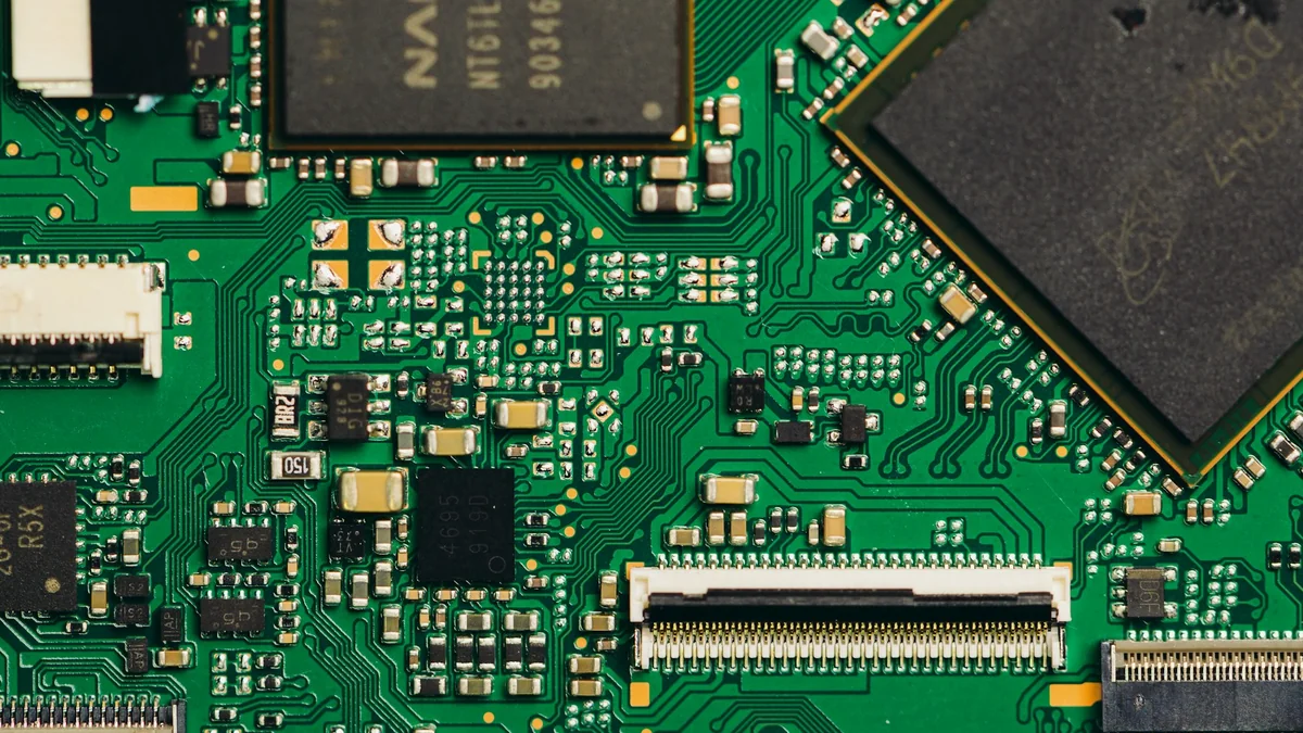
A fine-pitch PCBA quotation should explain the stencil plan as well as component placement. A board with a small QFN, a BGA and large connectors may need different paste volumes on the same side. Before approving tooling, agree on aperture geometry, foil thickness and trial-print evidence. A minimum-pitch claim alone does not establish that your particular board will print consistently.
Start with the exact packages and released board data
Send the assembler the BOM with manufacturer part numbers, paste and solder-mask layers, fabrication drawing, assembly drawing and panel information under one revision. Identify packages with special stencil instructions. Use the component manufacturer’s current package instructions for the footprint review. TI’s QFN/SON attachment guide explains why the land pattern and stencil geometry must be considered together. A CAD library footprint is therefore a starting point, not approval of the paste pattern.
Ask who owns the final stencil edits. Keep a marked-up drawing showing every change from the supplied paste layer, with design-team approval before cutting tooling.
Compare thickness, aperture area and release together
Area ratio compares the opening area with the aperture-wall area. For an idealized rectangular aperture with straight walls:
AR = (w × l) / [2 × t × (w + l)], where width w, length l and foil thickness t use the same unit. Nominal aperture volume is w × l × t.
For an opening measuring 0.20 × 0.80 mm:
| Thickness | Area ratio | Nominal volume |
|---|---|---|
| 0.10 mm | 0.800 | 0.0160 mm³ |
| 0.12 mm | 0.667 | 0.0192 mm³ |
The thinner foil improves this geometric release indicator but reduces nominal volume. Indium’s print-metrics guide describes 0.66 as a conventional benchmark. It is a screening reference, not a production guarantee. Rounded or tapered openings require their actual geometry to be reviewed.
Specify the paste and stencil as a process combination
Ask the paste supplier to review the smallest opening and proposed powder type. Choosing finer powder simply because a component has a smaller pitch can miss other constraints. AIM’s reduced-powder study discusses benefits alongside shelf-life, oxide and reflow-coalescence concerns. A powder change should trigger a paste-handling and reflow review.
Record the foil material, aperture manufacture, wall finish and any coating in the tooling specification. Compare these with the actual paste formulation and cleaning method. AIM’s stencil-technology study shows that coating, paste chemistry and compatible underside wiping affected release in its experiment. Those results justify evaluating the combination; they do not guarantee the same improvement on another board.
Resolve mixed-component volume conflicts before ordering
A foil selected for the smallest aperture may leave larger joints short of paste; increasing thickness may make the small openings harder to release. List the components that drive each requirement and ask the assembler to propose a documented compromise. TI’s attachment guide notes that the other surface-mount devices on a board also influence the stencil-thickness decision.
If a stepped stencil is proposed, request the local thickness map and the stencil supplier’s spacing constraints around each transition. Confirm that both printing and cleaning can accommodate that design before purchasing it.
Review QFN thermal-pad windows and vias together
Do not automatically copy the full exposed copper pad into one paste opening. TI’s QFN/SON attachment guide explains that excess central-pad solder can lift the component and create opens. Its segmented stencil examples regulate volume and support outgassing. Use the exact package recommendation to develop the window pattern, then verify it through assembly trials.
Review that pattern against the thermal-via locations and specified via treatment. Open vias can remove solder from the joint, while plugging or tenting introduces different fabrication and voiding considerations. TI recommends consulting the board fabricator rather than treating one via treatment as universally correct.
Record the approved window layout, via construction and inspection criteria on the same revision. A stencil change cannot compensate for an unresolved thermal or fabrication requirement. For the later inspection discussion, see our X-ray and void-control guide.
Approve trial evidence, then freeze the settings
Solder paste inspection (SPI) should assess deposited volume and position, not merely whether paste is visible. Transfer efficiency is measured deposit volume divided by nominal aperture volume, as defined in Indium’s inspection guidance.
For the trial, request results by critical component or aperture group across several prints. Include restart after a representative pause and the planned cleaning cycle. Compare variation and repeatability as well as averages. Agree on the sample size and acceptance limits before running the trial; one attractive print is weak evidence for production.
Then check assembled trial boards using the agreed inspection and electrical-test plan. SPI establishes printing evidence; reflowed joints need their own assessment. Our BGA assembly quality-control guide explains the broader inspection handoff.
A practical tooling-approval checklist
- Design owner: confirm package variants, footprint revision, paste layers, thermal intent and approved edits.
- Assembler: confirm foil thickness, aperture dimensions, paste product, printing setup and board support.
- Stencil supplier: confirm manufacture, wall finish, dimensional tolerances and any step transitions.
- PCB fabricator: confirm solder-mask constraints and the specified thermal-via treatment.
- Both teams: approve trial scope, SPI limits, assembled-board acceptance criteria and the change-control owner.
For a PCBA quotation, include the released files and identify the packages that need stencil review. Ask for a tooling proposal and validation plan tied to that board revision. This gives purchasing and engineering a concrete basis for approval before production starts.
Technical references
- Indium Corporation — Stencil Printing for SMT Assembly Success Part 2: Print Metrics
- AIM Solder — Impact of Reduced Alloy Powder Size on Paste Print Performance
- AIM Solder — A Study to Determine the Impact of Solder Powder Mesh Size and Stencil Technology on Deposition Volume
- Texas Instruments SLUA271C — QFN and SON PCB Attachment, revised December 2023