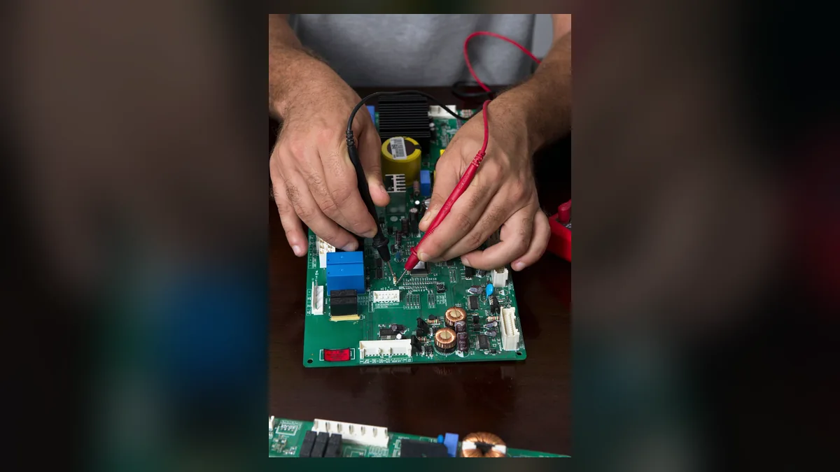
Short answer: PCBA testing should prove the risks that inspection alone cannot: electrical connections, programmed behavior, interfaces, calibration, and—in selected products—reliability under a defined stress profile. The useful test plan is not the one with the most steps; it is the one that states what each step proves, what it cannot prove, and what record is retained.
What each PCBA test is for
| Method | Best at finding | Use it when | Boundary to state |
|---|---|---|---|
| Visual inspection / AOI | Assembly workmanship, polarity, missing or visibly misplaced parts | Every build needs documented assembly acceptance controls | It does not prove electrical or system behavior. |
| ICT or flying-probe test | Opens, shorts, selected values and accessible-net faults | There is adequate test access; fixture cost and repeat quantity justify the approach | Coverage is limited by probes, access, programming and the test specification. |
| Functional circuit test (FCT) | Power-up, communications, I/O, sensor response and product-specific behavior | The product requirements and pass/fail limits are defined | It can show that a function passed in the stated setup, not every possible field condition. |
| Programming / calibration | Correct firmware revision, configuration and measured adjustment | Firmware or calibrated parameters are controlled deliverables | Revision control, calibration reference and retained result must be specified. |
| Burn-in / stress screen | Specified early-life or intermittent-failure risks | A product risk assessment defines temperature, duration, load and acceptance rules | Do not call it reliability proof without a defined qualification method and evidence. |
Choose the test mix by risk, not by a generic checklist
A prototype may begin with controlled manual checks, a known-good reference unit, and targeted measurements while the design is still changing. A repeat build with stable access and enough volume may justify ICT or a dedicated fixture. Functional testing becomes essential when the buyer needs evidence that the assembled product starts, communicates, measures, or controls as required. Combining a structural check with a functional test often shortens fault isolation, but the combination is only worthwhile when its coverage, cost, and ownership are agreed in advance.
Before fixture design, define the PCB revision, test points, power sequence, interfaces, firmware image, limits and tolerances, golden-sample policy, fault disposition, data retention, fixture ownership, maintenance responsibility, and forecast quantity. If one of these inputs is undecided, record it as an RFQ assumption rather than presenting a test promise as settled.
Inspection, workmanship, and functional proof are different claims
Acceptance inspection and functional verification answer different questions. IPC describes J-STD-001 as covering soldering processes and materials, and IPC-A-610 as post-assembly acceptance criteria. A product-specific test plan must separately define functional pass/fail limits, ownership, retest rules, and retained evidence; visual acceptance by itself is not proof of product behavior.
Make test results traceable and reviewable
For a serialised build, agree whether the retained record will connect the unit serial number to the test program revision, operator or station, timestamp, PASS/FAIL result, measured values, firmware revision, and relevant material or build lot. The right record is product-specific: collect the fields needed for containment and root-cause analysis, then protect customer and product data according to the agreed access rules.
For build-level reporting, use the PCBA assembly yield report template to keep first-pass yield, rework, and final acceptance distinct.
When inspection finds an unexpected condition, retain the original evidence before adjusting the process. The SMT defect troubleshooting guide sets out the observations, configuration records and follow-up checks needed to test a proposed cause.