HOME-02 · Connected Home
Robotic Lawn Mower Control and Power PCBA
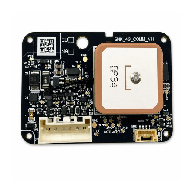
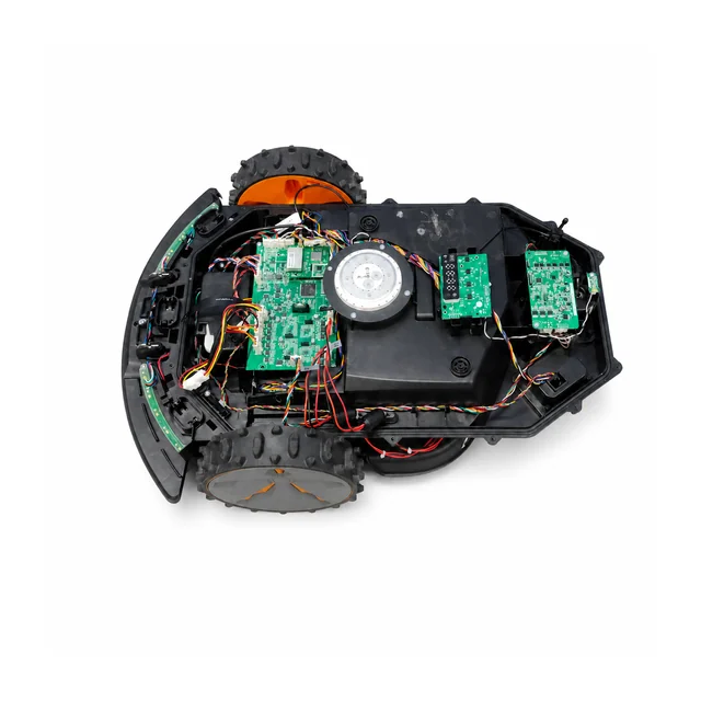
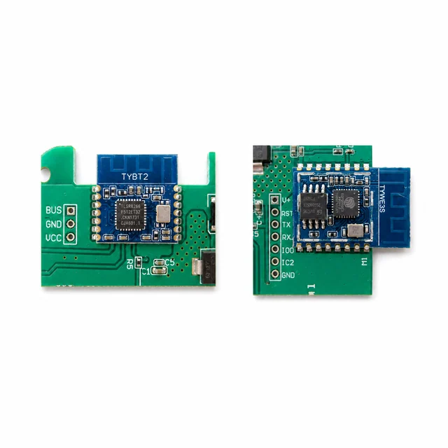
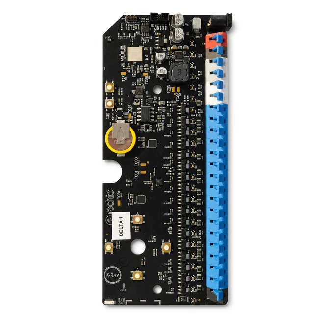
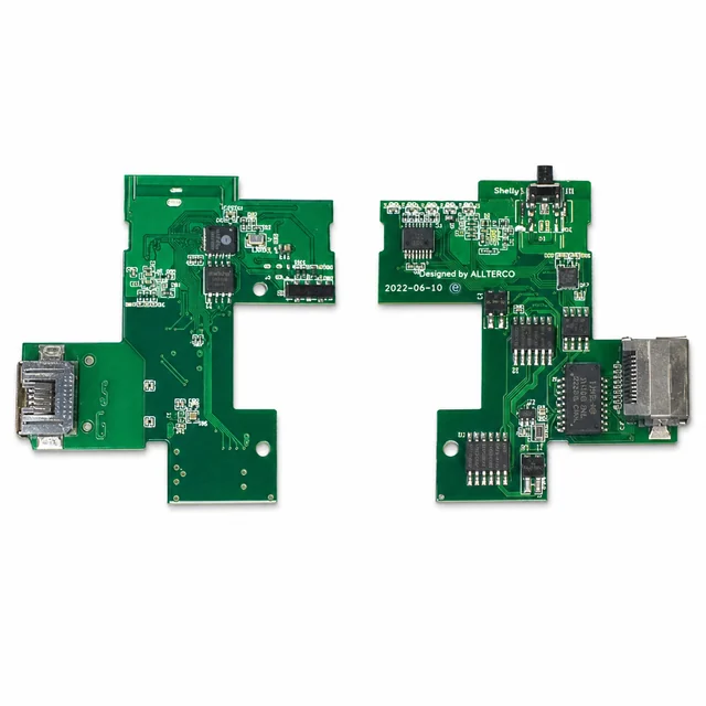
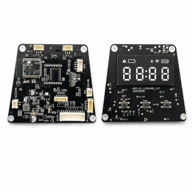
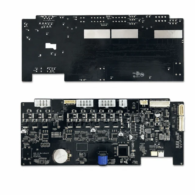
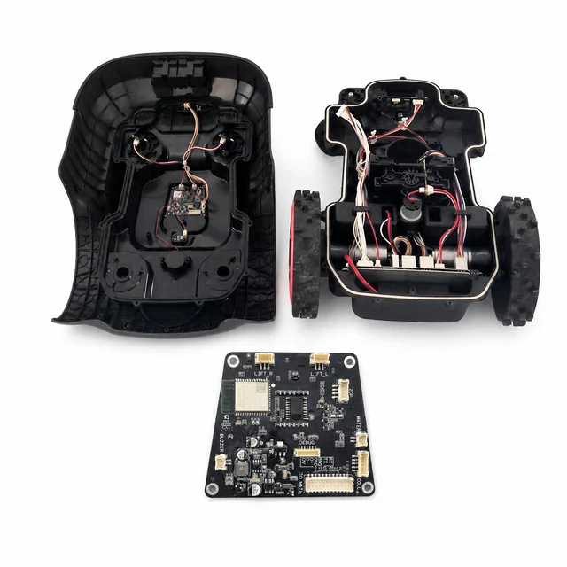
An FCC-photo reference spanning the RLM1000 control board, user-interface board, wireless section, labeled safety and sensor connectors, and a large mainboard with repeated power channels.
Project context
How this product is typically engineered
An FCC-photo reference spanning the RLM1000 control board, user-interface board, wireless section, labeled safety and sensor connectors, and a large mainboard with repeated power channels.
System architecture
Typical architecture
A representative battery platform distributes a protected high-current bus to traction, blade, and auxiliary actuators while DC/DC rails power the real-time controller, sensor interfaces, wireless board, and display; safety inputs arbitrate every motion command locally.
Engineering risks to resolve
Decisions to close before release
- Handle motor-start, stall, and regenerative transients without disturbing sensing or wireless control.
- Guarantee rapid blade shutdown for lift, tilt, collision, or internal-communication faults.
- Survive condensation, mud, fertilizer contamination, vibration, and sealed-enclosure thermal loading.
Validation plan
Checks to define before production
- Inject lift, tilt, collision, sensor-disagreement, motor-stall, and communication-timeout faults.
- Measure blade stopping time, slope start and stop behavior, charging faults, and full-load temperature rise.
- Run rain, ingress, damp-heat, corrosion, vibration, motor-EMC, ESD, EFT, and wireless-coexistence tests.
What to put in the RFQ
Files and records to agree before quoting
Use this list to agree the build inputs and release records for a similar product. The final set depends on the project.
Design baseline
Released schematic or block diagram, interface table, power states, critical constraints, and revision owner.
Manufacturing release
Gerber or ODB++, stack-up, centroid data, assembly drawings, approved DFM dispositions, and panel assumptions.
Material control
Released BOM revision, manufacturer part numbers, AVL or alternate rules, no-substitute lines, MSL handling, and exception approvals.
Validation record
Test method, acceptance criteria, sample or serial identity, measured result fields, and disposition. Example scope: Inject lift, tilt, collision, sensor-disagreement, motor-stall, and communication-timeout faults.
Production release
First-article status plus the agreed SPI, AOI, X-ray, ICT, FCT, programming, rework, OQA, labeling, and packing records.
During RFQ review, we confirm the required fields, sampling, limits, approvals, and record-retention period. Confidential project information stays within the agreed access rules.
Development and production controls
Typical manufacturing scope
- Multi-axis motor and actuator control.
- Safety-sensor and UI integration.
- Outdoor power-electronics development.
Technical image review
Board-level evidence
White-background views are published to make component placement, interfaces and assembly boundaries easier to inspect.