LWC8-A02 · V0.11 / V10 ENGINEERING REVIEW
8-zone leak detection controller PCBA
Locate the affected zone, retain the alarm and report system health.
A common monitoring platform for equipment rooms, buildings, industrial facilities and warehouses. Sensor choice, cable length, installation and operating limits are qualified for each project.
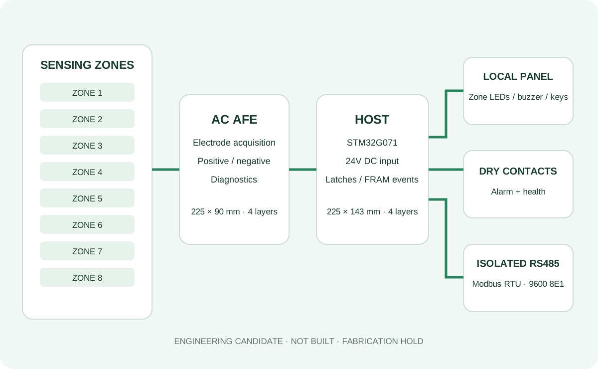
8 sensing zones24V DC input2 relay functionsIsolated RS485
Who uses it
Detect water ingress across separated areas and connect local alarms to the building or equipment monitoring system.
Equipment-room operators
Equipment manufacturers
Factory facilities teams
Warehouse operators
Property service providers
Monitoring & alarm behavior
Zone-level detection
AC electrode acquisition and separate continuity/health measurements distinguish leak evidence from measurement faults. Sensor and wiring qualification remains required.
Alarm latching
Confirmed leaks set retained alarm latches. Recovery alone does not clear the latch; dry and healthy conditions are required for reset.
Independent health output
The health relay withdraws on invalid acquisition, continuity or system faults. Contact states and timing still require target-board verification.
Local panel
Zone LEDs, a buzzer, silence/reset keys and a heartbeat support local inspection. A new event cancels mute.
Service records
FRAM records and Modbus expose confirmed/candidate states, fault masks, electrode data and event counts.
Controlled maintenance
SERVICE gates maintenance actions. The supplied service reader sends FC04 only and preserves raw frames.
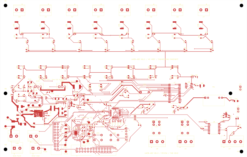
Native PCB preview
Interfaces & integration
| Interface | Design scope |
|---|---|
| Input | 24V DC system; 18–30V is a proposed bench boundary, not a qualified product rating. |
| Sensing | 8 zones through the AC acquisition board; actual probes, cables and environmental limits must be validated. |
| Panel | Zone indicators, buzzer and silence/reset; 26-contact interface. |
| Alarm / health | Two relay functions; load/contact compatibility and switching behavior require testing. |
| Communication | Isolated RS485 / Modbus RTU, 9600 8E1, default address 1. |
| Maintenance | 5-contact SWD and service control; program/readback and first FRAM initialization remain unexecuted. |
What has been verified
- HOST, AFE and panel: native ERC/DRC and unconnected counts are zero, without waived checks.
- Firmware: isolated GCC build passed with warnings treated as errors; rebuilt 9492-byte BIN exactly matches the retained candidate.
- Interfaces: 34 MCU GPIO roles and 46 design harness contacts match the current source maps.
- Service protocol: 100 current-C-generated synthetic response frames and local transport fault checks passed. These are software checks.
What remains before physical release
Manufacturer confirmation of MOS lead pitch/fit and drain-tab insulation, board stack and connector orientation, and AUX thermal-via fill/cap process. Then build samples and execute the 22 insertion measurements, 16 target-board tests, six protection cases and applicable thermal/EMC/FCT/installation checks.
Engineering downloads
Download without registration. The complete V10 review ZIP preserves the frozen engineering bundle; categorized files are review extracts. All are held engineering material, not a manufacturing release.
Complete V10 engineering review & editable sourceZIP · 15423.0 KB ↓KiCad source & local librariesZIP · 1291.0 KB ↓Firmware, read-only service tool & protocol test sourceZIP · 461.7 KB ↓DFM, population, harness & held review exportsZIP · 841.9 KB ↓HOST position BOMCSV · 40.2 KB ↓46-contact harness mapCSV · 5.6 KB ↓MCU pins & netsCSV · 1.7 KB ↓First programming & commissioning guideTXT · 6.6 KB ↓16 target-board cases — not testedCSV · 2.7 KB ↓6 protection cases — not testedCSV · 0.7 KB ↓Native HOST CAD drawingSVG · 964.5 KB ↓
Develop a leak monitoring PCBA for your project
Send the sensing arrangement, probe/cable requirements, power source, alarm contacts, building-system interface, enclosure, environment and expected quantities. We can define a project-specific design and sample validation plan.
Discuss OEM development ↗