Heated storage and mixing tanks
Use the 100 L atmospheric clean-water tank as the system example: 70 L working fill, 230 V / 3 kW heater, 65 °C default setpoint and a fixed-speed circulation pump. The process setting spans 20–85 °C.
PROCESS CONTROL · TANK-CTRL-A02
Published engineering candidate. Prototype, system and EMC validation remain pending. Control temperature, liquid level, pressure and flow in one heated-water system. A 24 V board connects the field instruments, operator panel and external power cabinet, with detailed accessory selections and downloadable technical files.
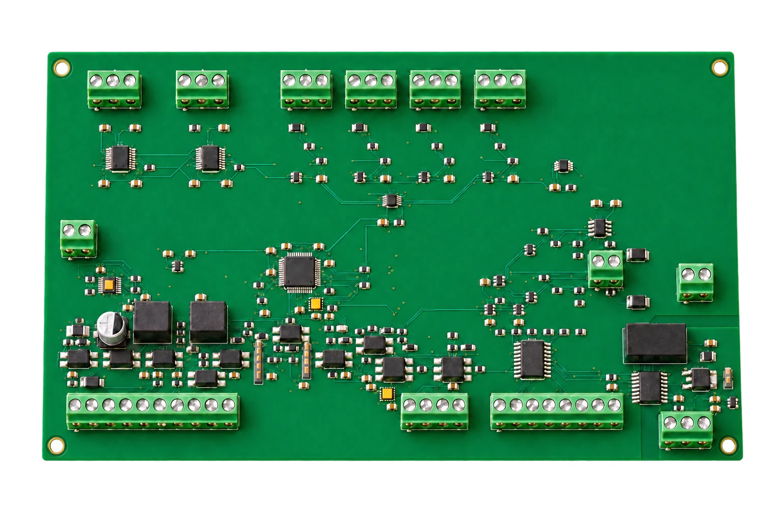
Use the 100 L atmospheric clean-water tank as the system example: 70 L working fill, 230 V / 3 kW heater, 65 °C default setpoint and a fixed-speed circulation pump. The process setting spans 20–85 °C.
Temperature control combines two three-wire Pt100 probes with circulation flow proof. Continuous level measurement handles filling, while independent low/high level switches provide permissives and stop the inlet valve.
Adapt the interfaces for other tank sizes, heat loads and pumping arrangements. Industrial furnaces need a separate high-temperature sensor front end, power-stage sizing and process protection design; this water-tank configuration uses Pt100 probes.
The 215 × 130 mm, four-layer board uses an STM32G474RET6 controller, two MAX31865 Pt100 interfaces, an ADS1115 analog front end and MCP4728-based analog outputs. TPS26600 input protection and TMUX7412F analog protection are included. Field I/O uses 24 V; mains power stays in the external cabinet.
| Interface | Quantity / signal | Use in the tank example |
|---|---|---|
| Power | 24 V DC | J1; external protected branch |
| Temperature | 2 × three-wire Pt100 | Main liquid temperature + independent process cross-check |
| Analog inputs | 4 × 4–20 mA | AI1 pressure / AI2 level / AI3 flow; AI4 spare |
| Analog outputs | 2 × 0–10 V | Expansion; unused for fixed-speed pump |
| Digital inputs | 8 × 24 V PNP | Level, flow, contactors, pressure, lid, E-stop, hardware permit |
| Digital outputs | 6 × low-side | SSR, contactor command, pump, fill valve, spare, alarm |
| Pulse inputs | 2 channels | Expansion |
| Communication | Isolated RS485 | Modbus RTU operator panel |
A start request moves through filling and circulation proof before heating. The PI loop defaults to Kp = 5 and Ki = 0.02, with a 2 s zero-cross SSR window. Tune the loop to the installed tank, mixing and thermal losses. Fault reset clears the fault latch; it does not start the heater.
Flow ≥3 L/min and a continuous 1 s flow-switch proof precede heating. Pressure ≥0.30 bar, software temperature ≥90 °C, lost permissives, stale sensor data, contactor feedback faults or a 30 min fill timeout stop the process. The independent STB trips at 95 °C and uses manual reset below 90 °C.
The system selection contains 71 per-unit purchasing lines and 11 factory-tool lines. Models, quantities, installation constraints and manufacturer URLs are recorded for each item. The table below exposes every line; the workbook provides the full purchasing layout. Configured probes and custom metalwork use the listed ordering specifications and matching interface drawings.
Selection and installation notes are translated from the Chinese engineering source. Model codes, quantities and limits are unchanged; the original Chinese notes remain available in the Chinese page and purchasing workbook.
| ID / function | Manufacturer / model | Quantity | Specification & installation |
|---|---|---|---|
| T1/T2 Main/cross-check liquid-temperature probes | ifm TM4431 ↗ | 2 pcs | Pt100 Class A; G1/2; insertion 100mm; liquid temperature -40..150°C 3-wire connection: M12 1/2 on the same end, 3 on the other end, 4 insulated; position H300mm |
| T3/T4 Independent overtemperature probes | JUMO 902006/10-402-1003-1-9-100-104/000 ↗ | 2 pcs | 1×Pt100 3-wire; Ø9×100mm; G1/2 compression fitting; -40..400°C Model recommended in the 701150 manual; confirm the current order code/probe combination with JUMO; install at H160mm near the heater |
| LT Continuous level transmitter | ifm PM1789 ↗ | 1 pc | -5..100mbar; set 4–20mA to 0..100mbar; hot water 85°C Flush-mounted at the bottom, H0; 16.30146mA≈800mm(ρ980); calibrate on the actual tank |
| PT Circulation-loop pressure transmitter | ifm PM1707 ↗ | 1 pc | -50..1000mbar; set 4–20mA to 0..1bar Branch downstream of the pump; AI1; measure the maximum normal pressure; alarm at 0.3bar |
| PS Independent pressure-permissive switch | ifm PI2799 ↗ | 1 pc | -1..1bar; medium -25..125°C; PNP OUT1 Hnc; SP1=0.30bar, rP1=0.20bar; OUT1→KPH and DI5; do not use KP35 |
| LSL/LSH Low/high level switches | ifm LMT100 ↗ | 2 pcs | PNP; G1/2 sealing cone; clean-water medium up to 100°C Low level H250: OUT1 wet=1; high level H680: OUT2 dry=1; hardware low-level permissive/fill stop |
| FT Flow meter | ifm SM6120 ↗ | 1 pc | G1/2 DN15; 0.05..35L/min; EPDM; medium up to 90°C OUT2=4–20mA/0..35; OUT1=Hno 3.0/2.5L/min; clean-water conductivity ≥20µS/cm |
| P1 Fixed-speed circulation pump | Grundfos 98485504 / COMFORT 15-14 B PM ↗ | 1 unit | 230V 50/60Hz; Rp1/2; port-to-port distance 80mm; apply the 2..95°C limit Basic B model; do not use AUTOADAPT; short closed loop; verify 3..5L/min by measurement |
| YV1 Normally closed fill solenoid valve | Bürkert 20056292 / Type 6213 ↗ | 1 pc | DN13 G1/2;EPDM;24VDC;0..10bar;-30..90°C Install only on the cold-water supply; closes on power loss; upstream filtration and flow adjustment; confirm coil power for the final manufacturer order; valve current budget 0.75A |
| WYV1 Valve connector | Bürkert 314820 / Type 2518 ↗ | 1 pc | DIN EN175301-803 Form A; 24VAC/DC; LED+varistor; 10A; IP65 Includes seal/screw; 24V; connect 1(+)/2(-)/PE; provide 0.75mm² field wiring |
| PA1 Aseptoflex weld-in adapter | ifm E30122 ↗ | 3 pcs | Ø50mm Aseptoflex Vario; EPDM seal included 1 each for LT/PT/PS; follow the manufacturer's welding procedure and use the protective mandrel |
| PA2 Level-switch weld-in adapter | ifm E43300 ↗ | 2 pcs | G1/2 sealing-cone weld-in adapter For LMT100 only; do not replace the sealing cone with a standard G1/2 sleeve |
| PA3 Flow-meter pipe adapters | ifm E40199 ↗ | 1 pack | 2 pieces per pack; sensor G1/2 flat seal→pipe R1/2 Both ends of SM6120; check supplied flat seals/length; allow straight pipe 5D upstream and 2D downstream |
| V1..V4 Manual isolation/drain valves | Genebre 3028 04 ↗ | 4 pcs | DN15 G1/2 standard bore Ø14; Kv15; brass/PTFE/NBR; 110°C 1 isolation valve each upstream/downstream of the pump, 1 fill isolation valve, 1 bottom drain valve; fit a locking catch to the drain handle |
| SF1 Fill-line Y-strainer | Genebre 2460 04 ↗ | 1 pc | R/Rp1/2; 316/PTFE; PN40; removable, cleanable filter element Install before the fill valve; keep out of the low-head circulation loop |
| LS6 Tank-lid position switch | Telemecanique Sensors XCKM121 ↗ | 1 pc | Metal roller limit switch; 1NC+1NO; Pg11; IP66 30° cam; closing the lid closes 13/14 NO→DI6; mount on a bracket at ≤60°C |
| ID / function | Manufacturer / model | Quantity | Specification & installation |
|---|---|---|---|
| Q0 Main isolator | Schneider Electric A9S60232 ↗ | 1 pc | 2P 32A; DIN; lockable Two-pole disconnection of 230V L/N; continuous PE |
| QF0 Main residual-current/overcurrent protection | Schneider Electric A9DC3620 ↗ | 1 pc | 1P+N;C20;Type A;30mA;6kA Dedicated 20A site circuit; L/N orientation per nameplate; do not route PE through the neutral terminal |
| QF1 Heater-branch circuit breaker | Schneider Electric A9F84216 ↗ | 1 pc | 2P C16;Acti9 iC60H 3kW resistive load; 2.5mm²; test current at the 253V upper limit |
| QF2 Control-branch circuit breaker | Schneider Electric A9F84204 ↗ | 1 pc | 2P C4;Acti9 iC60H Power supply/pump/fan; measure HDR supply inrush and cold-start behavior |
| PSU 24V DIN power supply | Mean Well HDR-100-24 ↗ | 1 unit | 24V 3.83A/92W;85..264VAC Design peak budget ≤3.1A; inside cabinet ≤40°C; board eFuse cuts off OV30..36V |
| DC1..5 24V electronic branch protection | Phoenix Contact 2908262 / PTCB E1 24DC/1-8A NO ↗ | 5 pcs | 18..30VDC; set DC4 to 2A and the others to 1A; NO status contact 1 each for the PCB, HMI, sensors, safety chain, and combined valve/alarm branch; STB maximum 12W, do not set the safety chain to 1A; IN- powers the device itself only, load return goes to the 0V busbar |
| SSR1 AC heater SSR with heatsink | Omron G3PE-225B DC12-24 ↗ | 1 pc | Zero-cross; single-phase 25A@40°C; 75..264VAC; built-in heatsink; DIN Nominal 13.04A; control ≤7mA; B model; verify cabinet thermal test ≤40°C and check derating |
| K1/K2 Series heater contactors | Schneider Electric LC1D25BD ↗ | 2 pcs | 24VDC coil; 3NO; AC1 40A≤60°C; auxiliary 1NO+1NC Both L/N run in series through K1 and K2; built-in NC contacts for EDM, NO contacts in series→DI4 |
| SR1 Emergency-stop/restart-monitoring relay | Schneider Electric XPSUAF13AP ↗ | 1 pc | 24VAC/DC; dual NC inputs; monitored manual reset; 3NO safety outputs A1 powered through STB+low-level+pressure permissives; 13/14→K1, 23/24→K2, 33/34→DI8 |
| STB Independent overtemperature limiter | JUMO 00564208 / 701150/8-01-0253-2001-25/005,058 ↗ | 1 unit | 2×Pt100 3-wire; AC/DC20..30V; STB O-function; includes approval configuration 058 Trips at 95°C/manual reset below 90°C; 14/16 closed when healthy; German by default, retain configuration records |
| KR1..9 Interface relays with bases | Phoenix Contact 2966171 / PLC-RSC-24DC/21 ↗ | 9 pcs | 24VDC input 9mA; 1CO; 6A; DIN DO2, DO3, DO4, DO6: 1 each; 1 each for low-level, high-level, pressure and emergency-stop health; KR9 in parallel with DI8 ensures SR1 output ≥10mA |
| HMI 7-inch operator panel | Weintek MT8072iP V2 ↗ | 1 unit | 800×480; 24V350mA; COM2 RS485; cutout 192×138mm 19200/8E1; station 1; connected to PCB; Windows EBPro 6.10.02.421 |
| S0 Dual-NC emergency-stop button | Schneider Electric XB5AS8444 ↗ | 1 set | Ø22/40mm; twist release; 2NC 2NC to the two SR1 channels; fit a yellow emergency-stop legend plate |
| S0A Additional NC contact for emergency-stop monitoring | Schneider Electric ZBE102 ↗ | 1 pc | 1NC screw-terminal contact block; XB5 compatible DC5 third contact→P_ES health; DI7/KR8/valve supply; check mechanical synchronization after assembly |
| S1/S2 Hardware reset buttons | Schneider Electric XB5AA61 ↗ | 2 pcs | Blue momentary; 1NO; Ø22 1 resets SR1 (through EDM), 1 provides external STB reset; do not reuse as software start |
| HLA Red fault indicator | Schneider Electric XB5AVB4 ↗ | 1 pc | 24VAC/DC LED;Ø22 Powered by the KR4 DO6 alarm contact; label as fault |
| HA Fault buzzer | Schneider Electric XB5KSB ↗ | 1 pc | 24VAC/DC; ≤28mA; Ø22; continuous/intermittent Powered by KR4 alarm contact; continuous warning; DO6 does not provide a mute command |
| ENC Steel control enclosure with mounting plate | Schneider Electric NSYS3D8630P ↗ | 1 set | 800×600×300mm; original enclosure IP66; mounting plate included Complete-cabinet target IP54 after HMI/fan installation; keep away from the tank steam outlet |
| FAN Filter fan and outlet grille | Schneider Electric NSYCVF85M230PF ↗ | 1 set | 230VAC; 85m³/h; G2 filter; IP54; outlet grille included Lower intake/upper exhaust; cutout per delivered drawing; test temperature rise with a clogged filter/stopped fan |
| TH Fan thermostat | Schneider Electric NSYCCOTHO ↗ | 1 pc | 0..60°C; NO contact; DIN Set fan start to 35°C; not for process-temperature protection |
| XTG Gray DIN terminals | Phoenix Contact 3209510 / PT 2.5 ↗ | 56 pcs | 2.5mm² Push-in; 24A; 800V; width 5.2mm Group per system wiring list; keep mains and 24V groups separate |
| XTB Blue DIN terminals | Phoenix Contact 3209523 / PT 2.5 BU ↗ | 24 pcs | 2.5mm² Push-in;24A Separate N and 0V zones; do not bridge the terminals |
| XTPE PE DIN terminals | Phoenix Contact 3209536 / PT 2.5-PE ↗ | 12 pcs | 2.5mm²; yellow/green; rail grounding Cabinet/door/tank/heater/pump/lid switch/probe head/sensor housing etc. per grounding schedule |
| XTEND Terminal end plates | Phoenix Contact 3030417 / D-ST 2.5 ↗ | 12 pcs | Gray; matched to PT2.5 Fit at every exposed group end; do not omit |
| XTCLIP DIN end stops | Phoenix Contact 3022276 / CLIPFIX 35-5 ↗ | 16 pcs | NS35 end stop 8 rail sections, 2 per section |
| XTBUS Terminal jumpers | Phoenix Contact 3030213 / FBS 10-5 ↗ | 4 pcs | 10 positions, 5.2mm; matched to PT2.5 Bridge equal potentials only; follow manufacturer derating after removing pins |
| RAIL 35mm perforated DIN rail | Phoenix Contact 0801733 / NS35/7.5 PERF 2000MM ↗ | 2 lengths | 2m×35×7.5mm; galvanized steel Total cut length ≤3m; see layout for 8 section lengths; deburr cut ends |
| DB9 Panel-side RS485 connector | Phoenix Contact 2761499 / SUBCON9/F-SH ↗ | 1 pc | DB9 female; individual screw terminals for all pins; shielded housing pin2=D+, pin1=D-, pin5=GND; connect shell to shield, not to 24V |
| ID / function | Manufacturer / model | Quantity | Specification & installation |
|---|---|---|---|
| WC1 M12 sensor cables | ifm EVT001 ↗ | 8 cables | A-coded 4-pin straight female; 5m; no LED; PVC; -25..100°C T1/T2/LT/PT/PS/LSL/LSH/FT; each cable ≤5m after cutting; mark wire ends |
| WC2 High-temperature cable for independent probes | LAPP 00460033 / ÖLFLEX HEAT 180 SiHF 4G0.75 ↗ | 10m | 4G0.75mm² silicone; 180°C T3/T4: 5m each; brown/blue/black for 3-wire RTD, PE to metal head only; equal lengths and cross-sections |
| RS485 RS485 cable | Belden 3106A.00152 ↗ | 2m | 120Ω; 22AWG twisted pair+reference+shield; maximum 60°C Supplied as a 152m reel or a 2m cut from an authorized channel; keep away from heater wiring; single-point shell PE |
| ACIN Main power lead | LAPP 1119403 / ÖLFLEX CLASSIC 110 3G2.5 ↗ | 3m | 3G2.5mm²;300/500V Dedicated fixed 20A site circuit; no standard 10A/16A plug; nominal outside diameter 8.0mm |
| HEATWIRE Heater lead | LAPP 0046020 / ÖLFLEX HEAT180 SiHF 3G2.5 ↗ | 3m | 3G2.5mm²; silicone 180°C; 300/500V Junction box ≤100°C; protective earth on metal housing; do not suspend the load by the cable |
| PUMPWIRE Pump/valve/lid-switch leads | LAPP 0046002 / ÖLFLEX HEAT180 SiHF 3G0.75 ↗ | 9m | 3G0.75mm²;180°C 3m each; lid switch needs only 2 cores+PE; do not use PE as a signal conductor |
| GLAND16 M16 cable glands | LAPP 53111010 / SKINTOP ST-M16×1.5 ↗ | 13 pcs | Clamping Ø4..10mm; gray; PA 8 M12 cables+2 independent RTDs+pump+valve+lid switch, total 13; separate Pg11 gland at the lid-switch end |
| GLAND20 M20 cable glands | LAPP 53111020 / SKINTOP ST-M20×1.5 ↗ | 2 pcs | Clamping Ø6..13mm 1 each for main power/heater; matching locknuts/seals |
| FERRULE075 0.75mm² ferrules | Phoenix Contact 3200519 / AI0.75-8 GY ↗ | 180 pcs | Tube length 8mm; strip wire to the terminal's specified length For 0.34mm² sensor wires, do not force-fit 0.75 ferrules; select separate 0.34 ferrules |
| FERRULE25 2.5mm² ferrules | Phoenix Contact 3200522 / AI2.5-8 BU ↗ | 36 pcs | Tube length 8mm Heater/main-power/grounding schedule; verify crimp pull strength |
| INTERNALWIRE Internal cabinet wiring kit | Purchase to this project's drawings/specifications TANK-WCAB-A02 | 1 pack | H07V-K 2.5 brown 5m/blue 5m/yellow-green 5m; 0.75 brown 10m/blue 15m/black 15m; 0.34 shielded signal extension ≤2m Specify IEC60228 Class5; inside cabinet ≤60°C; mains and low-voltage signals in separate ducts |
| DUCT Covered wiring duct | Purchase to this project's drawings/specifications TANK-DUCT-A02 | 1 pack | Flame-retardant PVC V0; 40×60×2000mm, 2 lengths; slot pitch 8mm; covers included Cut per cabinet drawing; separate AC/DC ducts; 20% spare capacity |
| GLANDKIT Gland locknuts/plugs | Purchase to this project's drawings/specifications TANK-GLANDKIT-A02 ↗ | 1 pack | M16 locknuts 13/M20 locknuts 2/EPDM panel seals 15; lid-switch Pg11 gland LAPP 53015020(Ø4..10)1 and EPDM face seal 1; M16 waterproof blanking plugs 2 Match LAPP gland thread type; Pg11 gland only for the XCKM121 field port; verify IP54 after cabinet cutouts; do not pass multiple cables through a standard single-hole gland |
| TINYFERRULE Fine-wire sensor ferrules | Purchase to this project's drawings/specifications TANK-AI0.34-8-A02 | 64 pcs | Tin-plated copper; 0.34mm²/8mm; insulated collar; DIN46228-4 For EVT001 0.34mm² wires only; terminal/wire pull-out test |
| PEKIT Protective-earthing hardware | Purchase to this project's drawings/specifications TANK-PEKIT-A02 | 1 pack | A2 M6×16 bolts 12/toothed washers 24/M6 nuts 12/tin-plated copper 2.5mm²-M6 ring terminals 24/yellow-green flexible door bonding strap 2.5mm²×300mm Remove paint at dedicated PE studs, use double toothed washers; secure against loosening; connection target ≤0.1Ω per test plan |
| PCBMOUNT PCB supports and touch-protection cover | Purchase to this project's drawings/specifications TANK-PCBMOUNT-A02 | 1 set | M3 male/female brass standoffs 12mm×4; M3×8 A2 screws 8/insulating shoulder washers 4; clear PC V0 cover 225×140×35mm PCB mounting-hole pattern: 206×121mm; installed inside the complete cabinet; do not bond 24V copper to PE; ventilated and protected against dropped screws |
| SEALKIT Pipe/flange sealing and fastener kit | Purchase to this project's drawings/specifications TANK-SEALKIT-A02 | 1 pack | DN65 PN16 EPDM full-face gasket 1+spare 1/316 M16×60 bolts 4+nuts 4+washers 8; G1/2 FKM flat seals 4; PTFE tape 12mm×0.1mm×10m, one roll Confirm flange GB/T9124.1 dimensions in agreed drawings; no PTFE tape on ifm sealing cones; check manufacturer-supplied seals separately at receiving |
| LABEL Labeling and fastening consumables kit | Purchase to this project's drawings/specifications TANK-LABEL-A02 | 1 pack | Wire markers 200/device labels 80/yellow emergency-stop plate 1/hot-surface labels 4/equipment nameplate 1/316 pipe clamps DN15×8/cable ties 100/tie mounts 20/DIN mounting M4 sets 32 Serial number/3kW230V/atmospheric pressure/process ≤85°C; water- and heat-resistant labels; keep ties away from hot pipes |
| WT3T4 Independent RTD harness assembly | Purchase to this project's drawings/specifications TANK-WT3T4-A02 | 2 cables | 4G0.75 silicone stock 00460033, 5m each; RTD 3-core terminals, PE to connector shell T3→STB1/2/3, T4→6/7/8; same-end wire pairs to 2/3 and 7/8 |
| HARNESS Cabinet harness assembly/terminal labeling | Purchase to this project's drawings/specifications TANK-WIRESET-A02 | 1 set | Build line by line from the system-wiring CSV; low-voltage signals 0.75/sensors 0.34; mains 2.5; match all terminals and wire numbers Raw materials counted separately; do not count materials again in labor items; 100% continuity/miswiring/PE inspection |
| JUMPER Termination jumper and HMI resistor | Purchase to this project's drawings/specifications TANK-TERM-A02 | 1 pack | 2.54mm shorting cap 1; 120Ω1%0.25W axial resistor 1; insulating heat-shrink sleeves 2 Close PCB JP1; at the HMI DB9 1/2, add 120Ω; terminate at the two bus ends only |
| ID / function | Manufacturer / model | Quantity | Specification & installation |
|---|---|---|---|
| TANK Atmospheric tank assembly | Purchase to this project's drawings/specifications TANK-V100-A02 | 1 set | 316L; inner Ø400×effective straight height 800; shell 2mm/bottom 3mm; volume 100.53L; insulation 25mm; legs 250mm Working volume 70L; overflow H720; open DN25 vent without a valve; matching port schedule/dimensional drawing |
| H1 Immersion heater | Purchase to this project's drawings/specifications TANK-H1-230-3000-A02 | 1 set | 230V/3kW±3%; 316L Ø14; 3U; cold section 35/straight sections 310, 285, 260/U-bend R20; insertion from outer end 372; bundle diameter ≤56; DN65PN16 flange H100; total effective length ≥1.898m; parallel power sections 1080/1000/920W; nominal surface load ≤3.6W/cm²; PE stud; IP65 junction box; verify sample fit |
| PIPE DN15 circulation/fill/drain pipe kit | Purchase to this project's drawings/specifications TANK-PIPE-DN15-A02 | 1 set | 316L pipe Ø21.3×2; circulation total length ≤2m/≤4 bends; ISO7-1 R/Rp1/2; 4 detachable union sets No filter/check valve in the circulation loop; separate flow adjustment+check valve on the cold-water fill side; pipe section dimensions per P&ID |
| LIMIT Fill-flow restriction-orifice assembly | Purchase to this project's drawings/specifications TANK-ORIFICE-2P6MM-A02 | 1 pc | 316L orifice plate; bore Ø2.6±0.05; DN15; removable Cold-water inlet 1..3bar, expected 2.8..4.8L/min; measured flow ≤5L/min; 30min fill timeout; 70L in about 25min |
| CHECK Cold-water fill check-valve assembly | Purchase to this project's drawings/specifications TANK-NRV-DN15-A02 | 1 pc | DN15 R/Rp1/2; 316L/EPDM; PN10; cracking pressure ≤0.05bar; medium 120°C Supplier to quote this complete specification and provide certificates; keep out of the circulation loop |
| INVENT Vent/overflow scald-protection drain kit | Purchase to this project's drawings/specifications TANK-VENT-OVERFLOW-A02 | 1 set | DN25 open gooseneck vent with removable coarse mesh; DN25 overflow to a safe tundish; total length of each ≤1m Two independent outlets without valves or fine filters; scald guard at discharge; do not seal the lid |
| ID / function | Manufacturer / model | Quantity | Specification & installation |
|---|---|---|---|
| WELD Aseptoflex welding mandrel | ifm E30452 ↗ | 1 pc | G1 Aseptoflex Vario; matched to E30122 Unscrew after factory welding, clean and inspect sealing surfaces; not supplied with the product |
| DBG Programming/debug probe | ST STLINK-V3MINIE ↗ | 1 set | STDC14 cable included; adapt to the board J2 five-pin connector J2=3V3 reference/SWDIO/SWCLK/GND/NRST; power the board from 24V; do not power it from the debug probe |
| IOSET Sensor configuration kit | ifm ZZ1060 ↗ | 1 set | AL1060+E12689+EVC012;USB IO-Link One-time factory equipment; moneo configure free; add E80121 if the available power is insufficient |
| CAL1 Current/voltage calibrator | Fluke 715 ↗ | 1 unit | 4/12/20mA and 0/5/10V tests Valid traceable calibration certificate required; for AI/AO |
| CAL2 Pt100 simulator/calibrator | Fluke 724 ↗ | 1 unit | Pt100 3-wire simulation; 20/65/85°C Test MAX31865 inputs and both STB channels |
| REF Actual-tank reference thermometer | Fluke 1551A-12 ↗ | 1 pc | -50..160°C; 12-inch probe; calibration certificate included Compare in a stirred water bath; probe immersion depth per manufacturer requirements |
| DMM Digital multimeter | Fluke 87V ↗ | 1 unit | Valid calibration; DC voltage/resistance Measure 24/12/5/3.3V and AO; use safety test leads |
| USB485 Isolated USB-RS485 adapter | Waveshare USB TO RS485 (B) ↗ | 1 pc | Isolated type; 19200/8E1 Use at a different time from the HMI; connect D+/D-/GND; do not connect VCC |
| IOPS External IO-Link power supply | ifm E80121 ↗ | 1 pc | 24VDC M12 A-coded power supply Required when ZZ1060 power is insufficient; not supplied with the product |
| TESTFIX Functional test fixture | Project-specific custom item TANK-FCT-A02 | 1 set | SWD adapter/J1..J15 connections/LED load 9mA/DI24V switches/5m high-temperature sensor cables See factory-test procedure; do not connect the actual heater; test matrix wiring before applying power |
| WIN Configuration workstation | Existing factory equipment or locally provided Windows11 x64 / EBPro6.10.02.421 ↗ | 1 unit | USB/Ethernet; 8GB RAM; offline software EBPro/JUMO/moneo configuration; USB and Ethernet interfaces |
Supply the board at J1 with 24 V DC and 0 V. Connect Pt100 probes to J4/J5 using equal-length three-wire leads. Supply instruments from the protected sensor branch; for AI1–AI3 leave connector pin 1 insulated, connect signal to pin 2 and return to pin 3. Low-side outputs drive the selected SSR input and intermediate relays, not mains loads.
230 V L/N → isolator Q0 → Type A RCBO QF0 → heater breaker QF1 → K1 → K2 → heater, with SSR1 in the L conductor after K2. Both contactors interrupt L and N. PE runs continuously to the cabinet, tank, pump and heater. Keep AC, 24 V, RTD and analog wiring in separate terminal groups and routes; do not bridge N to 0 V.
STB health, low-level health and pressure health feed SR1 through the independent hardware permit chain. Emergency-stop channels and contactor mirror contacts feed the restart monitor. Filling uses a normally closed valve with emergency-stop and high-level power interruption. Restoring a permit requires a deliberate reset and a separate start command.
Tank reference: 316L, inner Ø400 × 800 mm, 2 mm shell / 3 mm bottom, 25 mm insulation and 250 mm legs. H0 is the internal bottom. Heater H100; independent STB probes H160; low level H250; process Pt100 H300; working level H560; high level H680; overflow H720. Independent DN25 vent and overflow remain open, with an unsealed lid.
Use a short DN15 circulation loop, total length ≤2 m and ≤4 bends. Allow 5D upstream / 2D downstream of the flow meter. Keep the fill filter and check valve out of the low-head circulation loop. The selected pump must produce the required ≥3 L/min with the installed piping. SM6120 requires water conductivity ≥20 µS/cm; use a different measurement method for deionized water.
Weintek MT8072iP V2: 800 × 480 display, 192 × 138 mm panel cutout, 24 V supply. COM2 two-wire RS485 uses 19200 baud, 8E1, slave 1 and zero-based Modbus addressing. DB9 pin 2 D+ → J15.1 A; pin 1 D− → J15.2 B; pin 5 reference → J15.3 GND_ISO. Fit 120 Ω termination only at the two bus ends; bond the cable shield at the cabinet side.
Read holding registers 0–11 with FC03. Write the temperature setpoint at PDU 256 and a single command at 257 with FC06; command 1=start, 2=stop, 3=reset. Do not use FC16. Refresh every 500 ms; after three consecutive communication timeouts show stale data and inhibit start/setpoint writes. The operator screen does not replace the independent hardware permit chain.
| PDU address | Value | Scale / action |
|---|---|---|
| 0 / 1 | State / fault bits | Enumeration / bitmask |
| 2 / 3 | Main / cross-check liquid temperature | 0.01 °C; invalid = 0x8000 |
| 4 | Pressure | 0.0001 MPa |
| 5 / 6 | Level / flow | 0.01 % / 0.01 L/min |
| 7 / 8 | Setpoint / heating output | 0.01 °C / 0.01 % |
| 9 / 10 / 11 | DO bits / DI bits / firmware version | Bitmask / hexadecimal |
| 256 | Setpoint write · FC06 | 20–85 °C; 0.01 °C; RAM parameter |
| 257 | Command write · FC06 | 1 start / 2 stop / 3 reset |
3,000 W / 230 V = 13.04 A nominal heater current. For 70 kg of water from 20 to 65 °C, Q = m·cp·ΔT = 13.17 MJ; at 3 kW the ideal heating time is about 73 min. Heat losses, piping and mixing increase real heating time.
h = p / (ρ·g). With ρ = 980 kg/m³ and 0–100 mbar mapped to 4–20 mA, 800 mm corresponds to about 16.30 mA. Calibrate empty, working and upper levels on the actual tank; water density changes with temperature.
HDR-100-24 supplies 24 V / 3.83 A (92 W). The design load budget is ≤3.1 A; set DC4 for the safety chain to 2 A and the other four protected branches to 1 A. Fan thermostat starts at 35 °C; size airflow and SSR derating for a cabinet temperature ≤40 °C.
HMI native-project integration and manufacturing release remain open. The downloadable firmware images are EVT candidates, not production-release images. Download the complete KiCad, firmware, HMI, mechanical, wiring and factory documentation bundle, or choose individual files. The engineering handbook and purchasing workbook are in Chinese; interface tables use common signal names and model codes. File sizes and SHA-256 checksums are supplied for verification.
SHA-256 e58936c05eedea603ee02c7650327c54d3c262091daa33e2c2929ab1f2cd3602System engineering handbook · ChinesePDF · 344.4 KB ↓SHA-256 ce581f6dfa168178577fc90459d359c6f483f8bf60f428e5d163ec02ef3dc2e0Complete selection & purchasing workbook · ChineseXLSX · 55.8 KB ↓SHA-256 1bbdbdfb2cc2702009d01d7e6f47df58d815ce468fc1e29dc6c9f43d0e217e54Schematic · 10 sheetsPDF · 617.4 KB ↓SHA-256 24ac37dfd072168b7937fd5b1d1e8010e3bfb077978dbe10937cc11ec5c727a0PCB component BOMCSV · 35.4 KB ↓SHA-256 79e249326c1fef3d1f2bff5a4914a845b7666f4097eb39c9efd67afd7dfc3704System accessory BOMCSV · 22.6 KB ↓SHA-256 7c9ec0e8f7ce508efb05dd3dba897b1a5bec1ab9b0c85e9e335e37a8f770a8abWire-by-wire system listCSV · 7.5 KB ↓SHA-256 7a5b6e908370407b307b27c5520fd443affc866d32c703ee5296746ec33a9b9dBoard connector pinoutCSV · 4.8 KB ↓SHA-256 e386e2c7d71433d649eeebeacf45df1638ef3c45c23f98f1737ab326e86cbdc0HMI Modbus register mapCSV · 1.4 KB ↓SHA-256 2bcf903b2c9d8f9ff8e4fead5bb346b78474e47092ce1c0636a44b7f61fc5bbcFile manifest / checksumsJSON · 1.6 KB ↓SHA-256 0c7d7d347af93abbe54980ff16224741471e13aa68c7f63eec12a0800469bdb6Use the external SSR and contactors. The PCB uses 24 V field control and low-side outputs for the selected SSR input / relay coils. Follow the cabinet wiring file for the mains circuit.
This system example is an atmospheric clean-water tank with separate open vent and overflow. A pressure vessel or a different medium requires a different mechanical, sensor and protection specification.
Recalculate thermal energy, heater current and surface loading, select a matching SSR / contactor / cable / breaker combination, and size the pump from the complete loop resistance. Reposition the liquid-level and temperature instruments, then adjust limits and PI parameters.
Share the tank volume, medium, temperature range, heater supply and power, circulation flow, cabinet dimensions, operator-panel requirements and target quantity. These inputs define the board, harness, power cabinet and mechanical scope.
Discuss a process-control project ↗From our board gallery
Relay, display and controller boards from our own projects.