Heated storage and mixing tanks
Use the 100 L atmospheric clean-water tank as the system example: 70 L working fill, 230 V / 3 kW heater, 65 °C default setpoint and a fixed-speed circulation pump. The process setting spans 20–85 °C.
PROCESS CONTROL · TANK-CTRL-A02
Control temperature, liquid level, pressure and flow in one heated-water system. A 24 V board connects the field instruments, operator panel and external power cabinet, with detailed accessory selections and downloadable technical files.
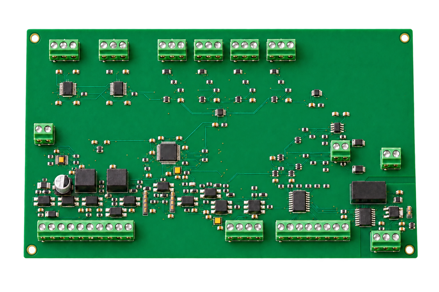
Use the 100 L atmospheric clean-water tank as the system example: 70 L working fill, 230 V / 3 kW heater, 65 °C default setpoint and a fixed-speed circulation pump. The process setting spans 20–85 °C.
Temperature control combines two three-wire Pt100 probes with circulation flow proof. Continuous level measurement handles filling, while independent low/high level switches provide permissives and stop the inlet valve.
Adapt the interfaces for other tank sizes, heat loads and pumping arrangements. Industrial furnaces need a separate high-temperature sensor front end, power-stage sizing and process protection design; this water-tank configuration uses Pt100 probes.
The 215 × 130 mm, four-layer board uses an STM32G474RET6 controller, two MAX31865 Pt100 interfaces, an ADS1115 analog front end and MCP4728-based analog outputs. TPS26600 input protection and TMUX7412F analog protection are included. Field I/O uses 24 V; mains power stays in the external cabinet.
| Interface | Quantity / signal | Use in the tank example |
|---|---|---|
| Power | 24 V DC | J1; external protected branch |
| Temperature | 2 × three-wire Pt100 | Main liquid temperature + independent process cross-check |
| Analog inputs | 4 × 4–20 mA | AI1 pressure / AI2 level / AI3 flow; AI4 spare |
| Analog outputs | 2 × 0–10 V | Expansion; unused for fixed-speed pump |
| Digital inputs | 8 × 24 V PNP | Level, flow, contactors, pressure, lid, E-stop, hardware permit |
| Digital outputs | 6 × low-side | SSR, contactor command, pump, fill valve, spare, alarm |
| Pulse inputs | 2 channels | Expansion |
| Communication | Isolated RS485 | Modbus RTU operator panel |
A start request moves through filling and circulation proof before heating. The PI loop defaults to Kp = 5 and Ki = 0.02, with a 2 s zero-cross SSR window. Tune the loop to the installed tank, mixing and thermal losses. Fault reset clears the fault latch; it does not start the heater.
Flow ≥3 L/min and a continuous 1 s flow-switch proof precede heating. Pressure ≥0.30 bar, software temperature ≥90 °C, lost permissives, stale sensor data, contactor feedback faults or a 30 min fill timeout stop the process. The independent STB trips at 95 °C and uses manual reset below 90 °C.
The system selection contains 71 per-unit purchasing lines and 11 factory-tool lines. Models, quantities, installation constraints and manufacturer URLs are recorded for each item. The table below exposes every line; the workbook provides the full purchasing layout. Configured probes and custom metalwork use the listed ordering specifications and matching interface drawings.
Detailed selection notes below are the Chinese engineering source. Model codes, quantities and manufacturer links are shared across languages.
| ID / function | Manufacturer / model | Quantity | Specification & installation |
|---|---|---|---|
| T1/T2 主控/复核液温探头 | ifm TM4431 ↗ | 2支 | Pt100 Class A;G1/2;插入100mm;液温-40..150°C 3线接法:M12 1/2同端,3为另一端,4绝缘;位置H300mm |
| T3/T4 独立超温用温度探头 | JUMO 902006/10-402-1003-1-9-100-104/000 ↗ | 2支 | 1×Pt100 3线;Ø9×100mm;G1/2压紧接头;-40..400°C 701150手册推荐型号;向JUMO确认当前订货码/探头组合;安装H160mm靠近加热器 |
| LT 连续液位变送器 | ifm PM1789 ↗ | 1只 | -5..100mbar;4–20mA设0..100mbar;热水85°C 底部齐平安装H0;16.30146mA≈800mm(ρ980),须按实罐标定 |
| PT 循环回路压力变送器 | ifm PM1707 ↗ | 1只 | -50..1000mbar;4–20mA设0..1bar 泵后支路;AI1;最大正常压力实测;报警0.3bar |
| PS 独立压力许可开关 | ifm PI2799 ↗ | 1只 | -1..1bar;介质-25..125°C;PNP OUT1 Hnc;SP1=0.30bar,rP1=0.20bar;OUT1→KPH及DI5;不采用KP35 |
| LSL/LSH 低/高液位开关 | ifm LMT100 ↗ | 2只 | PNP;G1/2密封锥;清水介质最高100°C 低位H250用OUT1湿=1;高位H680用OUT2干=1;硬件低液位/停止补水 |
| FT 流量计 | ifm SM6120 ↗ | 1只 | G1/2 DN15;0.05..35L/min;EPDM;介质最高90°C OUT2=4–20mA/0..35;OUT1=Hno 3.0/2.5L/min;清水电导率≥20µS/cm |
| P1 定速循环泵 | Grundfos 98485504 / COMFORT 15-14 B PM ↗ | 1台 | 230V 50/60Hz;Rp1/2;端面距80mm;按2..95°C限制 基础B型;不用AUTOADAPT;闭合短回路;3..5L/min必须实测 |
| YV1 常闭补水电磁阀 | Bürkert 20056292 / Type 6213 ↗ | 1只 | DN13 G1/2;EPDM;24VDC;0..10bar;-30..90°C 只装冷水供给侧;失电关;前置过滤和调流;线圈功率按厂家最终订货确认;阀电流预算0.75A |
| WYV1 阀连接器 | Bürkert 314820 / Type 2518 ↗ | 1只 | DIN EN175301-803 Form A;24VAC/DC;LED+压敏;10A;IP65 带密封件/螺钉;24V;接1(+)/2(-)/PE;现场配0.75mm²线 |
| PA1 Aseptoflex焊接接头 | ifm E30122 ↗ | 3只 | Ø50mm Aseptoflex Vario;随附EPDM密封 LT/PT/PS各1;采用厂家焊接步骤及保护芯轴 |
| PA2 液位开关焊接接头 | ifm E43300 ↗ | 2只 | G1/2密封锥焊接接头 只用于LMT100;不得用普通G1/2套管替代密封锥 |
| PA3 流量计接管附件 | ifm E40199 ↗ | 1包 | 每包2件;传感器G1/2平密封→管路R1/2 SM6120两端;核对随附平垫/长度;直管前5D后2D预留 |
| V1..V4 手动隔离/排水阀 | Genebre 3028 04 ↗ | 4只 | DN15 G1/2标准通径Ø14;Kv15;黄铜/PTFE/NBR;110°C 泵前/泵后隔离各1,补水隔离1,底部排水1;排水手柄加锁扣 |
| SF1 补水Y型过滤器 | Genebre 2460 04 ↗ | 1只 | R/Rp1/2;316/PTFE;PN40;可拆洗滤芯 装补水阀前;不放入低扬程循环回路 |
| LS6 罐盖位置开关 | Telemecanique Sensors XCKM121 ↗ | 1只 | 金属滚轮限位;1NC+1NO;Pg11;IP66 30°凸轮;盖闭合使13/14 NO闭合→DI6;安装在≤60°C支架 |
| ID / function | Manufacturer / model | Quantity | Specification & installation |
|---|---|---|---|
| Q0 总隔离开关 | Schneider Electric A9S60232 ↗ | 1只 | 2P 32A;DIN;可锁定 230V L/N双极断开;PE连续 |
| QF0 总漏电/过流保护 | Schneider Electric A9DC3620 ↗ | 1只 | 1P+N;C20;Type A;30mA;6kA 现场20A专用回路;L/N方向按铭牌;PE不穿中性端 |
| QF1 加热支路断路器 | Schneider Electric A9F84216 ↗ | 1只 | 2P C16;Acti9 iC60H 3kW电阻负载;2.5mm²;253V上限电流测试 |
| QF2 控制支路断路器 | Schneider Electric A9F84204 ↗ | 1只 | 2P C4;Acti9 iC60H 电源/泵/风扇;HDR电源浪涌与冷启动实测 |
| PSU 24V DIN电源 | Mean Well HDR-100-24 ↗ | 1台 | 24V 3.83A/92W;85..264VAC 设计峰值预算≤3.1A;箱内≤40°C;OV30..36V由板eFuse截止 |
| DC1..5 24V分支电子保护 | Phoenix Contact 2908262 / PTCB E1 24DC/1-8A NO ↗ | 5只 | 18..30VDC;DC4设2A,其余1A;带状态NO触点 PCB/HMI/传感器/安全链/阀报警各1;STB最大12W,安全链不可设1A;IN-只作自身供电,负载回流走0V母排 |
| SSR1 交流加热SSR带散热器 | Omron G3PE-225B DC12-24 ↗ | 1只 | 零交越;单相25A@40°C;75..264VAC;内置散热器;DIN 13.04A额定;控制≤7mA;B型号;箱内热试≤40°C并核查降额 |
| K1/K2 串联加热接触器 | Schneider Electric LC1D25BD ↗ | 2只 | 24VDC线圈;3NO;AC1 40A≤60°C;辅助1NO+1NC L/N均串联穿过K1及K2;内置NC用于EDM,NO串联→DI4 |
| SR1 急停/重启监控继电器 | Schneider Electric XPSUAF13AP ↗ | 1只 | 24VAC/DC;双NC输入;人工监控复位;3NO安全输出 A1受STB+低液位+压力许可供电;13/14→K1,23/24→K2,33/34→DI8 |
| STB 独立超温限制器 | JUMO 00564208 / 701150/8-01-0253-2001-25/005,058 ↗ | 1台 | 2×Pt100 3线;AC/DC20..30V;STB O-function;含058批准配置 95°C跳闸/低于90°C人工复位;14/16健康闭合;德语默认,配置留档 |
| KR1..9 中间继电器含底座 | Phoenix Contact 2966171 / PLC-RSC-24DC/21 ↗ | 9只 | 24VDC输入9mA;1CO;6A;DIN DO2、DO3、DO4、DO6各1;低液位、高液位、压力、急停健康各1;KR9并接DI8确保SR1输出≥10mA |
| HMI 7英寸操作屏 | Weintek MT8072iP V2 ↗ | 1台 | 800×480;24V350mA;COM2 RS485;开孔192×138mm 19200/8E1;站1;与PCB相连;Windows EBPro 6.10.02.421 |
| S0 双NC急停按钮 | Schneider Electric XB5AS8444 ↗ | 1套 | Ø22/40mm;旋转解锁;2NC 2NC至SR1双通道;须配黄色急停标牌 |
| S0A 急停监视附加NC | Schneider Electric ZBE102 ↗ | 1只 | 1NC螺钉接触模块;XB5兼容 DC5第三触点→P_ES健康;DI7/KR8/阀供电;装配后核查机械同步 |
| S1/S2 硬件复位按钮 | Schneider Electric XB5AA61 ↗ | 2只 | 蓝色瞬时;1NO;Ø22 1个复位SR1(经EDM),1个STB外部复位;不复用为软件启动 |
| HLA 故障红灯 | Schneider Electric XB5AVB4 ↗ | 1只 | 24VAC/DC LED;Ø22 KR4 DO6报警触点供电;标注故障 |
| HA 故障蜂鸣器 | Schneider Electric XB5KSB ↗ | 1只 | 24VAC/DC;≤28mA;Ø22;连续/间歇 KR4报警供电;持续警示;DO6不提供静音命令 |
| ENC 钢制控制箱带安装板 | Schneider Electric NSYS3D8630P ↗ | 1套 | 800×600×300mm;原箱IP66;含安装板 安装HMI/风扇后整柜目标IP54;远离罐体蒸汽出口 |
| FAN 过滤风扇+出口格栅 | Schneider Electric NSYCVF85M230PF ↗ | 1套 | 230VAC;85m³/h;G2过滤;IP54;含出口格栅 下进上出;实际开孔按到货图;滤堵/风扇停转温升试验 |
| TH 风扇温控器 | Schneider Electric NSYCCOTHO ↗ | 1只 | 0..60°C;NO触点;DIN 设35°C启动风扇;不承担过程温度保护 |
| XTG 灰色DIN端子 | Phoenix Contact 3209510 / PT 2.5 ↗ | 56只 | 2.5mm² Push-in;24A;800V;5.2mm宽 按系统接线清单分组,不合并主回路与24V |
| XTB 蓝色DIN端子 | Phoenix Contact 3209523 / PT 2.5 BU ↗ | 24只 | 2.5mm² Push-in;24A N与0V各自分区,端子不跨接 |
| XTPE PE DIN端子 | Phoenix Contact 3209536 / PT 2.5-PE ↗ | 12只 | 2.5mm²;黄绿;导轨接地 柜/门/罐/加热器/泵/盖开关/探头头/传感器壳等按接地表 |
| XTEND 端子端板 | Phoenix Contact 3030417 / D-ST 2.5 ↗ | 12只 | 灰色;PT2.5配套 每组裸露端安装;禁止遗漏 |
| XTCLIP DIN端挡 | Phoenix Contact 3022276 / CLIPFIX 35-5 ↗ | 16只 | NS35端挡 8段导轨每段2只 |
| XTBUS 端子跨接件 | Phoenix Contact 3030213 / FBS 10-5 ↗ | 4只 | 10位5.2mm;PT2.5配套 只跨同电位;切除脚后依厂家降额 |
| RAIL 35mm穿孔DIN导轨 | Phoenix Contact 0801733 / NS35/7.5 PERF 2000MM ↗ | 2根 | 2m×35×7.5mm;镀锌钢 总切长≤3m;8段尺寸见布置图;切口去毛刺 |
| DB9 屏端RS485接头 | Phoenix Contact 2761499 / SUBCON9/F-SH ↗ | 1只 | DB9母;全针独立螺钉;带屏蔽壳 pin2=D+,pin1=D-,pin5=GND;壳接屏蔽,不接24V |
| ID / function | Manufacturer / model | Quantity | Specification & installation |
|---|---|---|---|
| WC1 M12传感器线 | ifm EVT001 ↗ | 8条 | A-coded 4针母直头;5m;无LED;PVC;-25..100°C T1/T2/LT/PT/PS/LSL/LSH/FT;裁切后每条≤5m;线头标号 |
| WC2 独立探头高温线 | LAPP 00460033 / ÖLFLEX HEAT 180 SiHF 4G0.75 ↗ | 10米 | 4G0.75mm²硅胶;180°C T3/T4各5m;棕/蓝/黑为3线RTD,PE只接金属头;均长等截面 |
| RS485 RS485电缆 | Belden 3106A.00152 ↗ | 2米 | 120Ω;22AWG双绞对+参考线+屏蔽;最大60°C 供货152m卷或授权渠道裁切2m;远离加热线;单点壳PE |
| ACIN 主电源引线 | LAPP 1119403 / ÖLFLEX CLASSIC 110 3G2.5 ↗ | 3米 | 3G2.5mm²;300/500V 现场20A固定专用回路;无普通10A/16A插头;外径8.0mm级 |
| HEATWIRE 加热器引线 | LAPP 0046020 / ÖLFLEX HEAT180 SiHF 3G2.5 ↗ | 3米 | 3G2.5mm²;硅胶180°C;300/500V 接线盒≤100°C;金属壳保护接地;不悬空承重 |
| PUMPWIRE 泵/阀/盖开关引线 | LAPP 0046002 / ÖLFLEX HEAT180 SiHF 3G0.75 ↗ | 9米 | 3G0.75mm²;180°C 各3m;盖开关只需2芯+PE;不将PE作信号 |
| GLAND16 M16电缆格兰 | LAPP 53111010 / SKINTOP ST-M16×1.5 ↗ | 13只 | 夹持Ø4..10mm;灰色;PA 8条M12+2独立RTD+泵+阀+盖开关,共13;盖开关端另Pg11格兰 |
| GLAND20 M20电缆格兰 | LAPP 53111020 / SKINTOP ST-M20×1.5 ↗ | 2只 | 夹持Ø6..13mm 主电源/加热器各1;配同规格锁紧螺母/密封圈 |
| FERRULE075 0.75mm²管形端头 | Phoenix Contact 3200519 / AI0.75-8 GY ↗ | 180只 | 管长8mm;按端子剥线长度执行 传感器0.34mm²不得硬套0.75;另选0.34端头 |
| FERRULE25 2.5mm²管形端头 | Phoenix Contact 3200522 / AI2.5-8 BU ↗ | 36只 | 管长8mm 加热/主电源/接地表;压接拉力检验 |
| INTERNALWIRE 电柜内部线材包 | 按本项目图纸/规格采购 TANK-WCAB-A02 | 1包 | H07V-K 2.5棕5m/蓝5m/黄绿5m;0.75棕10m/蓝15m/黑15m;0.34屏蔽信号延长≤2m 明确IEC60228 Class5;柜内≤60°C;主回路与弱电不同线槽 |
| DUCT 带盖线槽 | 按本项目图纸/规格采购 TANK-DUCT-A02 | 1包 | 阻燃PVC V0;40×60×2000mm共2根;锯齿间距8mm;带盖 按柜图裁切;AC/DC分别走槽;余量20% |
| GLANDKIT 格兰配套锁母/塞子 | 按本项目图纸/规格采购 TANK-GLANDKIT-A02 ↗ | 1包 | M16锁母13/M20锁母2/EPDM面板密封圈15;盖开关Pg11格兰LAPP 53015020(Ø4..10)1及EPDM面密封圈1;M16防水堵头2 与LAPP格兰螺纹同制式;Pg11格兰仅用于XCKM121现场口;机柜开孔后实测IP54;不得多线共普通单孔格兰 |
| TINYFERRULE 传感器细线端头 | 按本项目图纸/规格采购 TANK-AI0.34-8-A02 | 64只 | 铜镀锡;0.34mm²/8mm;绝缘环;DIN46228-4 仅EVT001 0.34mm²线使用;端子和导线拉脱试验 |
| PEKIT 保护接地五金 | 按本项目图纸/规格采购 TANK-PEKIT-A02 | 1包 | A2 M6×16螺栓12/齿形垫圈24/M6螺母12/铜镀锡2.5mm²-M6环形端头24/黄绿门跨接软带2.5mm²×300mm PE独立螺柱去漆,双齿垫;防松;连接≤0.1Ω目标按测试方案 |
| PCBMOUNT PCB支撑及防触盖 | 按本项目图纸/规格采购 TANK-PCBMOUNT-A02 | 1套 | M3内外牙黄铜柱12mm×4;M3×8 A2螺钉8/绝缘肩垫4;透明PC V0护盖225×140×35mm 板孔206×121mm;整柜安装;不将24V铜箔搭PE;透气且防落螺钉 |
| SEALKIT 管路/法兰密封及紧固包 | 按本项目图纸/规格采购 TANK-SEALKIT-A02 | 1包 | DN65 PN16 EPDM全平垫1+备1/316 M16×60螺栓4+螺母4+垫片8;G1/2 FKM平垫4;PTFE密封带12mm×0.1mm×10m一卷 法兰GB/T9124.1尺寸由双方图确认;ifm密封锥不用PTFE带;厂家自带密封另核收料 |
| LABEL 标识及紧固耗材包 | 按本项目图纸/规格采购 TANK-LABEL-A02 | 1包 | 接线号200/器件号80/黄底急停牌1/热表面牌4/设备铭牌1/316管夹DN15×8/扎带100/扎带座20/DIN紧固M4套32 序列号/3kW230V/常压/工艺≤85°C;标签耐水耐热;绑线避开热管 |
| WT3T4 独立RTD线束加工 | 按本项目图纸/规格采购 TANK-WT3T4-A02 | 2条 | 4G0.75硅胶原料00460033,各5m;RTD3芯端子,PE接头壳 T3→STB1/2/3,T4→6/7/8;同端双线接2/3、7/8 |
| HARNESS 电柜线束加工/端子标号 | 按本项目图纸/规格采购 TANK-WIRESET-A02 | 1套 | 按系统接线CSV逐行加工;弱电0.75/传感器0.34;主电2.5;所有端子与线号一致 原材料另计,工时项目不重复计物料;100%导通/错线/PE检验 |
| JUMPER 端接跳帽及HMI电阻 | 按本项目图纸/规格采购 TANK-TERM-A02 | 1包 | 2.54mm短路帽1;120Ω1%0.25W轴向电阻1;绝缘热缩套2 PCB JP1闭合;HMI端DB9 1/2加120Ω;只在总线两端端接 |
| ID / function | Manufacturer / model | Quantity | Specification & installation |
|---|---|---|---|
| TANK 常压罐体总成 | 按本项目图纸/规格采购 TANK-V100-A02 | 1套 | 316L;内Ø400×有效直高800;壳2mm/底3mm;容积100.53L;25mm保温;支腿250mm 工作70L;溢流H720;敞开DN25通气无阀;端口表/尺寸图配套 |
| H1 浸入式加热器 | 按本项目图纸/规格采购 TANK-H1-230-3000-A02 | 1套 | 230V/3kW±3%;316L Ø14;3U;冷段35/直段310、285、260/U弯R20;外端插入372;束径≤56;DN65PN16法兰 H100;有效总长≥1.898m;功率1080/1000/920W并联;名义面负荷≤3.6W/cm²;PE螺柱;IP65接线盒;样件互配 |
| PIPE DN15循环/补水/排水管包 | 按本项目图纸/规格采购 TANK-PIPE-DN15-A02 | 1套 | 316L管Ø21.3×2;循环总长≤2m/≤4弯;ISO7-1 R/Rp1/2;可拆活接4套 循环不用过滤器/止回阀;补水另配调流+止回(冷水端);管路按P&ID分段尺寸 |
| LIMIT 补水限流孔组件 | 按本项目图纸/规格采购 TANK-ORIFICE-2P6MM-A02 | 1只 | 316L孔板;孔Ø2.6±0.05;DN15;可拆 冷水入口1..3bar预期2.8..4.8L/min;实测≤5L/min;30min补水超时;70L约25min |
| CHECK 冷水补水止回组件 | 按本项目图纸/规格采购 TANK-NRV-DN15-A02 | 1只 | DN15 R/Rp1/2;316L/EPDM;PN10;开启压≤0.05bar;介质120°C 供应商按此完整规格报价并提供证书;不在循环回路 |
| INVENT 通气/溢流防烫排水包 | 按本项目图纸/规格采购 TANK-VENT-OVERFLOW-A02 | 1套 | DN25敞开通气鹅颈带可拆粗网;DN25溢流至安全漏斗;总长度各≤1m 两个独立出口无阀无细滤;排放处防烫护罩;不密封盖 |
| ID / function | Manufacturer / model | Quantity | Specification & installation |
|---|---|---|---|
| WELD Aseptoflex焊接芯轴 | ifm E30452 ↗ | 1只 | G1 Aseptoflex Vario;E30122配套 工厂焊接后旋出/清理/检查密封面;不随产品交付 |
| DBG 烧录调试器 | ST STLINK-V3MINIE ↗ | 1套 | 含STDC14线;转接到板J2五针 J2=3V3参考/SWDIO/SWCLK/GND/NRST;板供电24V;不从调试器供电 |
| IOSET 传感器配置套件 | ifm ZZ1060 ↗ | 1套 | AL1060+E12689+EVC012;USB IO-Link 一次性工厂装备;moneo configure free;供电不足时外加E80121 |
| CAL1 电流/电压校准器 | Fluke 715 ↗ | 1台 | 4/12/20mA及0/5/10V测试 需有效溯源证书;用于AI/AO |
| CAL2 Pt100仿真校准器 | Fluke 724 ↗ | 1台 | Pt1003线仿真;20/65/85°C MAX31865输入及STB两通道测试 |
| REF 实罐温度参考 | Fluke 1551A-12 ↗ | 1支 | -50..160°C;12英寸探头;含校准证书 搅动水浴比对;探头插入深度按制造商要求 |
| DMM 数字万用表 | Fluke 87V ↗ | 1台 | 校准有效;直流电压/电阻 测24/12/5/3.3V与AO;配安全表笔 |
| USB485 隔离USB-RS485适配器 | Waveshare USB TO RS485 (B) ↗ | 1只 | 隔离型;19200/8E1 与HMI分时;接D+/D-/GND;不连VCC |
| IOPS IO-Link外置供电 | ifm E80121 ↗ | 1只 | 24VDC M12 A-coded电源 ZZ1060功率不足时必须接;不随产品交付 |
| TESTFIX 功能测试夹具 | 项目定制 TANK-FCT-A02 | 1套 | SWD转接/J1..J15插接/LED负载9mA/DI24V开关/5m高温传感器线 详见工厂测试;不连接真实加热器;矩阵接线先测后上电 |
| WIN 配置工作站 | 工厂已有/自配 Windows11 x64 / EBPro6.10.02.421 ↗ | 1台 | USB/以太网;8GB RAM;离线软件 EBPro/JUMO/moneo配置;USB与以太网接口 |
Supply the board at J1 with 24 V DC and 0 V. Connect Pt100 probes to J4/J5 using equal-length three-wire leads. Supply instruments from the protected sensor branch; for AI1–AI3 leave connector pin 1 insulated, connect signal to pin 2 and return to pin 3. Low-side outputs drive the selected SSR input and intermediate relays, not mains loads.
230 V L/N → isolator Q0 → Type A RCBO QF0 → heater breaker QF1 → K1 → K2 → heater, with SSR1 in the L conductor after K2. Both contactors interrupt L and N. PE runs continuously to the cabinet, tank, pump and heater. Keep AC, 24 V, RTD and analog wiring in separate terminal groups and routes; do not bridge N to 0 V.
STB health, low-level health and pressure health feed SR1 through the independent hardware permit chain. Emergency-stop channels and contactor mirror contacts feed the restart monitor. Filling uses a normally closed valve with emergency-stop and high-level power interruption. Restoring a permit requires a deliberate reset and a separate start command.
Tank reference: 316L, inner Ø400 × 800 mm, 2 mm shell / 3 mm bottom, 25 mm insulation and 250 mm legs. H0 is the internal bottom. Heater H100; independent STB probes H160; low level H250; process Pt100 H300; working level H560; high level H680; overflow H720. Independent DN25 vent and overflow remain open, with an unsealed lid.
Use a short DN15 circulation loop, total length ≤2 m and ≤4 bends. Allow 5D upstream / 2D downstream of the flow meter. Keep the fill filter and check valve out of the low-head circulation loop. The selected pump must produce the required ≥3 L/min with the installed piping. SM6120 requires water conductivity ≥20 µS/cm; use a different measurement method for deionized water.
Weintek MT8072iP V2: 800 × 480 display, 192 × 138 mm panel cutout, 24 V supply. COM2 two-wire RS485 uses 19200 baud, 8E1, slave 1 and zero-based Modbus addressing. DB9 pin 2 D+ → J15.1 A; pin 1 D− → J15.2 B; pin 5 reference → J15.3 GND_ISO. Fit 120 Ω termination only at the two bus ends; bond the cable shield at the cabinet side.
Read holding registers 0–11 with FC03. Write the temperature setpoint at PDU 256 and a single command at 257 with FC06; command 1=start, 2=stop, 3=reset. Do not use FC16. Refresh every 500 ms; after three consecutive communication timeouts show stale data and inhibit start/setpoint writes. The operator screen does not replace the independent hardware permit chain.
| PDU address | Value | Scale / action |
|---|---|---|
| 0 / 1 | State / fault bits | Enumeration / bitmask |
| 2 / 3 | Main / cross-check liquid temperature | 0.01 °C; invalid = 0x8000 |
| 4 | Pressure | 0.0001 MPa |
| 5 / 6 | Level / flow | 0.01 % / 0.01 L/min |
| 7 / 8 | Setpoint / heating output | 0.01 °C / 0.01 % |
| 9 / 10 / 11 | DO bits / DI bits / firmware version | Bitmask / hexadecimal |
| 256 | Setpoint write · FC06 | 20–85 °C; 0.01 °C; RAM parameter |
| 257 | Command write · FC06 | 1 start / 2 stop / 3 reset |
3,000 W / 230 V = 13.04 A nominal heater current. For 70 kg of water from 20 to 65 °C, Q = m·cp·ΔT = 13.17 MJ; at 3 kW the ideal heating time is about 73 min. Heat losses, piping and mixing increase real heating time.
h = p / (ρ·g). With ρ = 980 kg/m³ and 0–100 mbar mapped to 4–20 mA, 800 mm corresponds to about 16.30 mA. Calibrate empty, working and upper levels on the actual tank; water density changes with temperature.
HDR-100-24 supplies 24 V / 3.83 A (92 W). The design load budget is ≤3.1 A; set DC4 for the safety chain to 2 A and the other four protected branches to 1 A. Fan thermostat starts at 35 °C; size airflow and SSR derating for a cabinet temperature ≤40 °C.
Download the complete KiCad, firmware, HMI, mechanical, wiring and factory documentation bundle, or choose individual files. The engineering handbook and purchasing workbook are in Chinese; interface tables use common signal names and model codes. File sizes and SHA-256 checksums are supplied for verification.
SHA-256 e58936c05eedea603ee02c7650327c54d3c262091daa33e2c2929ab1f2cd3602System engineering handbook · ChinesePDF · 344.4 KB ↓SHA-256 ce581f6dfa168178577fc90459d359c6f483f8bf60f428e5d163ec02ef3dc2e0Complete selection & purchasing workbook · ChineseXLSX · 55.8 KB ↓SHA-256 1bbdbdfb2cc2702009d01d7e6f47df58d815ce468fc1e29dc6c9f43d0e217e54Schematic · 10 sheetsPDF · 617.4 KB ↓SHA-256 24ac37dfd072168b7937fd5b1d1e8010e3bfb077978dbe10937cc11ec5c727a0PCB component BOMCSV · 35.4 KB ↓SHA-256 79e249326c1fef3d1f2bff5a4914a845b7666f4097eb39c9efd67afd7dfc3704System accessory BOMCSV · 22.6 KB ↓SHA-256 7c9ec0e8f7ce508efb05dd3dba897b1a5bec1ab9b0c85e9e335e37a8f770a8abWire-by-wire system listCSV · 7.5 KB ↓SHA-256 7a5b6e908370407b307b27c5520fd443affc866d32c703ee5296746ec33a9b9dBoard connector pinoutCSV · 4.8 KB ↓SHA-256 e386e2c7d71433d649eeebeacf45df1638ef3c45c23f98f1737ab326e86cbdc0HMI Modbus register mapCSV · 1.4 KB ↓SHA-256 2bcf903b2c9d8f9ff8e4fead5bb346b78474e47092ce1c0636a44b7f61fc5bbcFile manifest / checksumsJSON · 1.6 KB ↓SHA-256 0c7d7d347af93abbe54980ff16224741471e13aa68c7f63eec12a0800469bdb6Use the external SSR and contactors. The PCB uses 24 V field control and low-side outputs for the selected SSR input / relay coils. Follow the cabinet wiring file for the mains circuit.
This system example is an atmospheric clean-water tank with separate open vent and overflow. A pressure vessel or a different medium requires a different mechanical, sensor and protection specification.
Recalculate thermal energy, heater current and surface loading, select a matching SSR / contactor / cable / breaker combination, and size the pump from the complete loop resistance. Reposition the liquid-level and temperature instruments, then adjust limits and PI parameters.
Share the tank volume, medium, temperature range, heater supply and power, circulation flow, cabinet dimensions, operator-panel requirements and target quantity. These inputs define the board, harness, power cabinet and mechanical scope.
Discuss a process-control project ↗