WTD-CTRL-A01 · FLOW DOSING
Water-treatment dosing controller PCBA
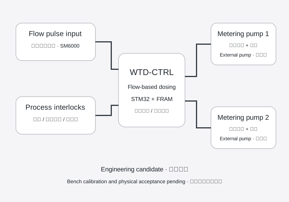
A flow-proportional dosing controller candidate for metering-pump equipment manufacturers, pool equipment suppliers and small water-treatment integrators. External pumps use isolated pulse and enable controls; low-level and process inputs interlock dosing.
- 18–30V
- DC board supply
- 2 pumps
- External pulse / enable controls
- STM32G071
- MCU with persistent FRAM records
- R35 / R34
- Factory handoff / station tools
Current engineering status
Updated 8 October 2026. Editable PCB, firmware, harness and adapter sources are packaged for factory review. 46 host test groups passed, including 24,876 modelled FRAM byte-interruption checks. The complete handoff archive has been freshly extracted and verified.
No real board programming, metering calibration, production release or field acceptance is evidenced. Tests and file hashes establish software or package checks; they do not establish real stopping, dosing accuracy or hardware qualification.
Control scope and customization
| Flow proportional dosing | Flow pulses drive configured metering commands, subject to timing, quota and process interlocks. |
|---|---|
| External metering pumps | Two channels of isolated pulse and enable interfaces; pump power and motor drive remain in the external equipment. |
| Low-level alarm and stop | Low-level and process inputs inhibit the affected output; both channels require real stopping tests. |
| pH / conductivity | Later transmitter integration scope. ADC and RS485 are currently disabled; water-quality closed loop is not implemented. |
| OEM variants | Pump input profile, flow pulse scaling, display, wiring, enclosure and calibration workflow are application-specific. |
Hardware and wiring references
| MCU / storage | STM32G071CBT6 and FM24CL64B-G; paired settings and dose-quota journal. |
|---|---|
| Reference equipment | ProMinent gamma/X GMXa1602 metering pump and ifm SM6000 flowmeter; verify actual full order codes and configured modes. |
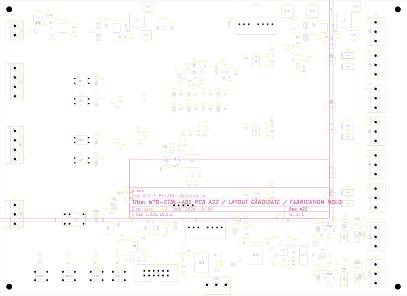
| Mainboard interfaces | J1 supply, J2 flow input, J8/J9 pump interfaces, J14 display, J15 SWD. Exact terminal maps are in the factory package. |
| Factory fixture | TP6 SCL / TP7 SDA; independent reset clamp and pump isolation. Adapter +5V must remain physically disconnected. |
Factory station and recovery
R34 adds supervised full MCU/FRAM capture, paired write transactions and controlled forward recovery. First manufacturing initialization requires traceable new-material and never-operated records, independent factory authorization hashes and matching MCU UID. Unknown history stays on hold; used-board quotas must not be reset.
Current station software is a macOS/POSIX candidate. Factory qualification with actual STM32CubeProgrammer, official Aardvark library, fixture and board is pending; Windows supervision is not implemented. The package does not redistribute official vendor tools.
Factory acceptance next steps
- Return DFM comments, actual PCB/PCBA receipts, board identity and component lot evidence.
- Keep pumps and dosing paths isolated for supply, reset/watchdog, interface and full device-capture checks.
- Measure both output channels and real stopping; calibrate pump stroke volume and flow pulse scaling under recorded conditions.
- Complete wiring/mechanical, environmental/EMC and application-specific field acceptance.
Engineering downloads
R35 is the complete entry point. It contains the unchanged R28 engineering baseline and R34 station tools. Blank return forms are templates, not actual factory results.
Discuss your dosing equipment
Share the pump interface, flowmeter profile, dosing range, alarms, enclosure and required quantities to define the development scope.
Discuss OEM development ↗