Four independent valve outputs
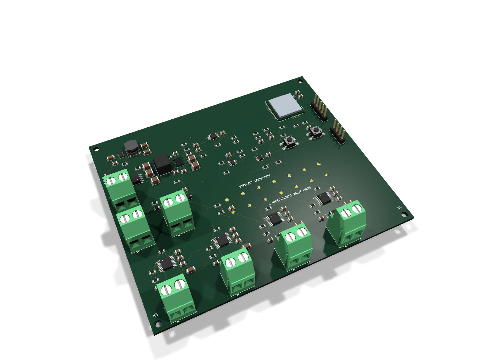
Separate two-wire connections drive four DC latching valves with polarity-reversing pulses. Sequential zone control coordinates the watering sequence.
DESIGN CASE · CONNECTED AGRICULTURE
A four-zone irrigation control design that brings valve drive, field power, wireless communication and sensor interfaces into one system.
01
Separate two-wire connections drive four DC latching valves with polarity-reversing pulses. Sequential zone control coordinates the watering sequence.
A protected LiFePO4 battery supplies the controller. A dedicated solar charger connects the panel to the battery, with power monitoring included in the board design.
The field controller communicates through a LoRa gateway. EU868 and US915 configurations address different deployment regions.
A wired rain switch and an optional pulse-output flow meter connect environmental feedback and water-use measurement to the control system.
02
The controller is one part of the irrigation system. The design coordinates the power path, four valve connections, sensor inputs and wireless link.
03
Valve outputs, power conversion, the radio controller and sensor connections are arranged on one board.
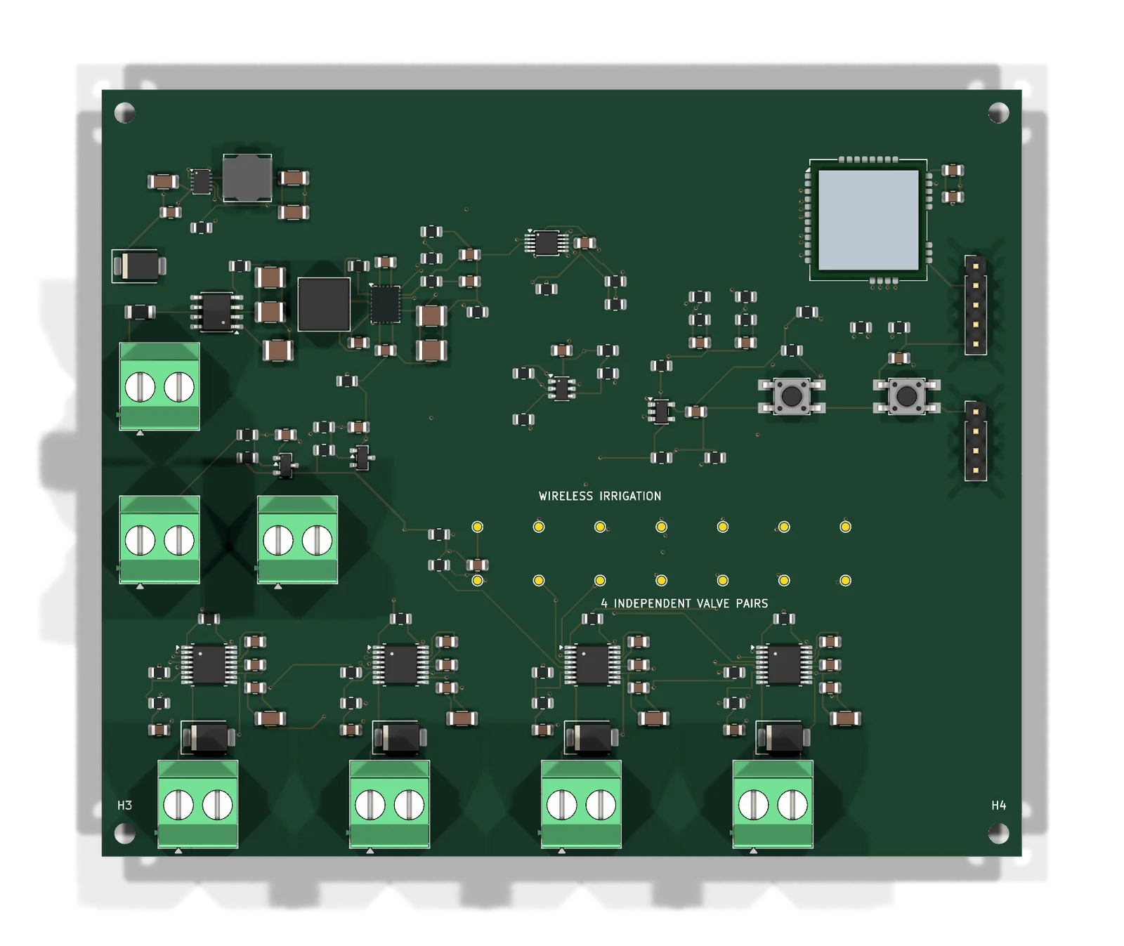
The accessory plan covers valve bodies and DC latching solenoids, a battery and solar panel, a dedicated charger, the antenna and gateway, a rain switch, an optional flow meter, and the enclosure with its cable glands and harnesses.
| Four DC latching valves | Four independent two-wire outputs |
|---|---|
| Battery and solar panel | Dedicated charger → battery → controller |
| Rain switch | Wired dry-contact input |
| Optional flow meter | Pulse-output interface |
| Antenna and gateway | EU868 or US915 LoRa configuration |
| Enclosure and harnesses | Cable glands and separate valve wire pairs |
Valve thread type, regional radio configuration, charging parameters, sensor signal type and cable length are coordinated with the installation requirements. Each valve uses its own wire pair; the solar panel connects through the charger.
Share your valve type, number of zones, installation country, power source and gateway arrangement. Include cable lengths, sensor needs and expected quantities to define the electronics and accessory scope.