Case and mounting dimensions
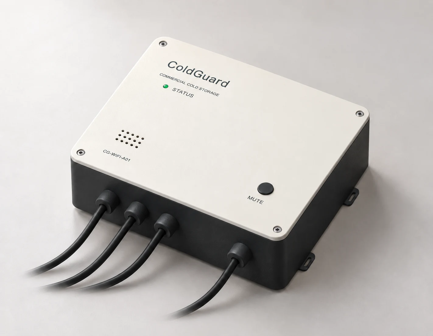
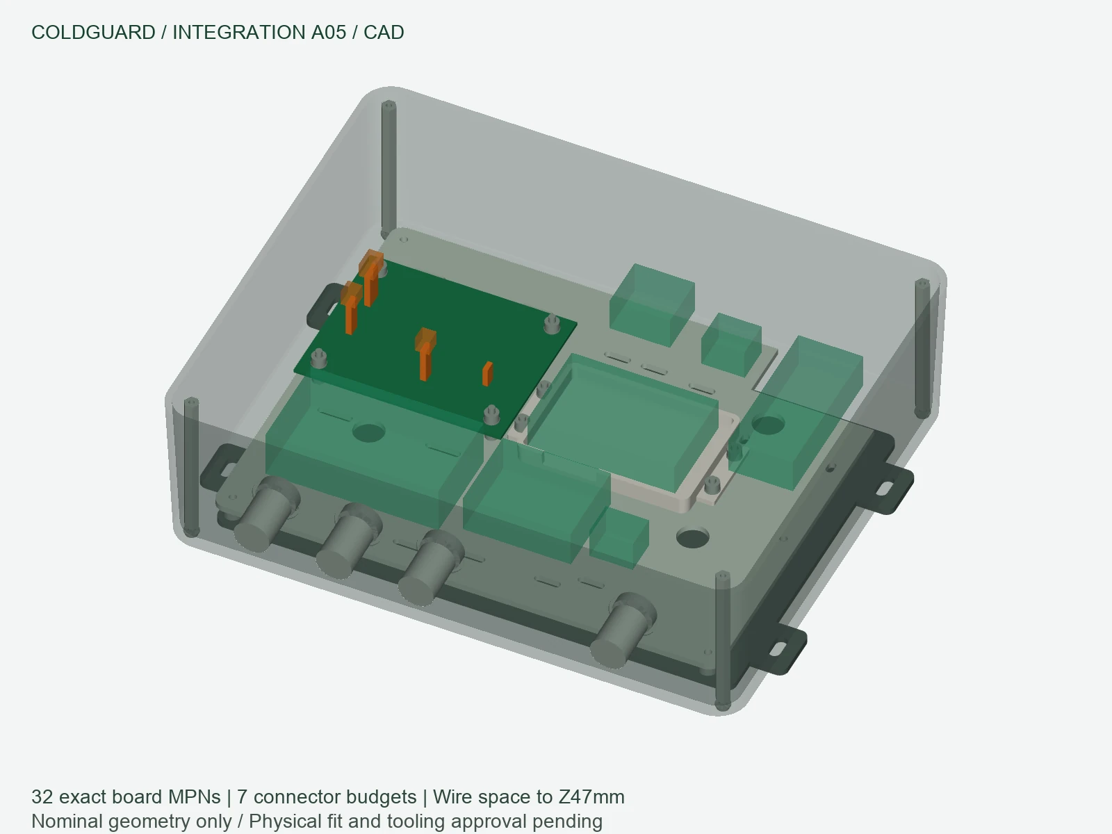
The main case is 270 × 220 × 78 mm with a warm-white lid and graphite base. A removable carrier, battery tray and aluminium backplate support servicing. Allow 90 mm total depth for the case, rear mounting and front-button seal space; bottom glands project another 22 mm before cable bends. Mount the electronics outside the refrigerated space in a dry location.
Cable glands and complete jackets
Four bottom ports serve T1, T2, door contact and 5 V. LAPP SKINTOP STR-M 53111300 M12 × 1.5 glands accommodate 2–5 mm cable diameters and pair with 53119100 nuts. A Ø22 mm inner spotface leaves a 2 ± 0.1 mm local wall target for the 8 mm thread and 5 mm nut. Each gland clamps one intact round jacket; select probe-jacket diameter accordingly. Use LiYY 0028302 for the room-side door extension and 0028402 for a 5 V extension no longer than 1 m.
Removable front accessories
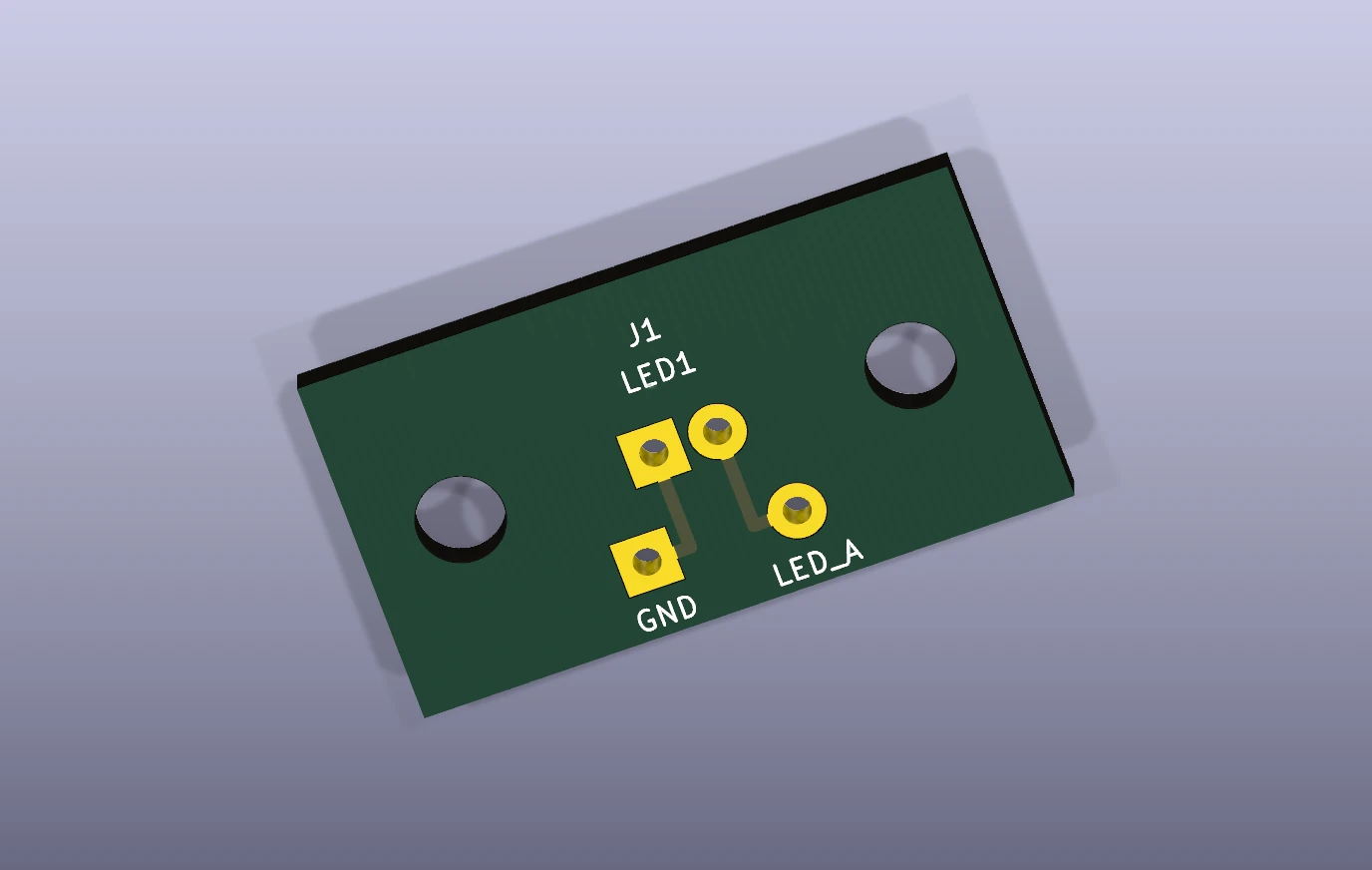
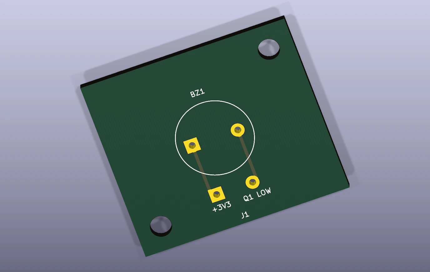
A Kingbright WP710A10GD green LED sits on a 26 × 14 × 1.6 mm daughterboard with 2.6 mm POM spacers and DIN 7991 M3 × 16 screws. The PUI AI-1223-TWT-3V-2-R buzzer sits on a 34 × 30 × 1.6 mm board with 8.7 mm spacers and M3 × 20 screws. Its 7.5 mm nominal body height gives a 1.2 mm nominal sound-face gap behind the lid. Four Ø3.4 mm mount holes use Ø6.2 mm, 90° countersinks, 1.4 mm deep; screw heads must sit flush. These are drawing targets, including the tolerance stack in the assembly manual.
Electrical drive and service harness
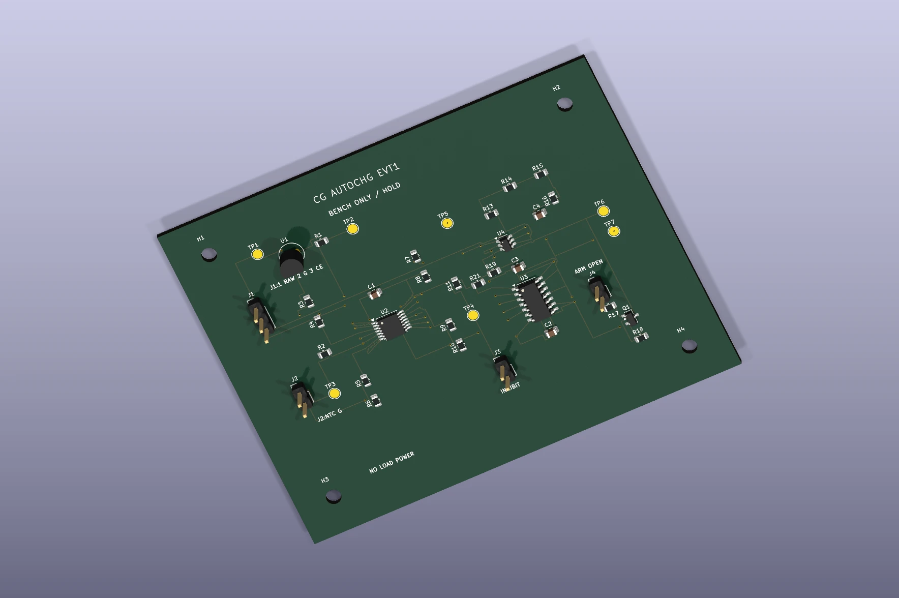
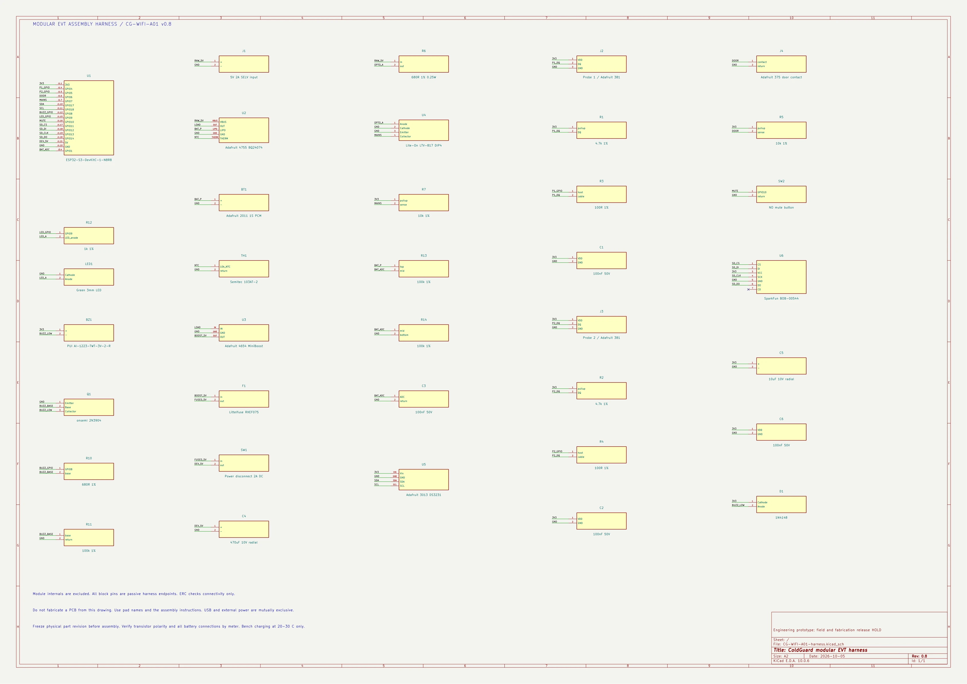
The LED daughterboard receives LED_A from GPIO9 through the existing R12 1 kΩ resistor and GND. The buzzer receives 3V3 and BUZZ_LOW from the existing Q1 collector, retaining the transistor and protection circuit. Daughterboards use two-layer 1.6 mm FR4 and 1 oz copper; KiCad sources, Gerbers and separate plated/non-plated drill files are supplied. Insulate each exposed lead individually and leave service slack so opening the lid does not pull solder joints.
Button, backplate and access
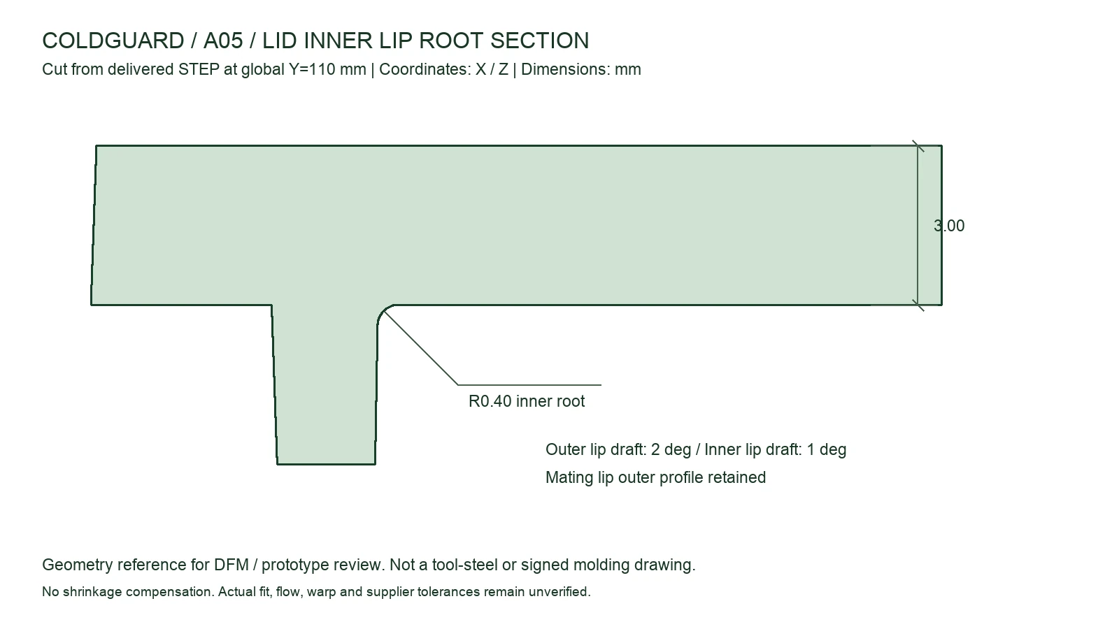
The APEM ISP3SAD200 mute button uses a double-flat Ø13.6 mm cutout with 12.9 mm flat width in the 3 mm lid. A 3 mm 5052-H32 aluminium backplate uses 6 mm rear spacers and recessed DIN 7991 M4 × 20 fasteners. Use suitable brackets and mounting surfaces, avoiding blind drilling into refrigeration cabinets. The 234 × 184 mm carrier separates controller, power, clock and storage; the battery envelope is 68 × 44 × 16 mm.
Radio, acoustic and cleaning conditions
Keep the controller antenna toward the enclosure edge and the recommended 15 mm RF region clear of metal and wiring. Check the installed signal path near metal cabinets. The open buzzer outlet and LED opening suit dry external installation; gland component ratings do not establish a whole-device ingress rating. Sites exposed to spray or condensation need a sealed acoustic/indicator arrangement, compatible materials and a cleaning-specific enclosure design.