Pump equipment OEM
Integrate pressure control, alternation, contactor feedback and local operating records into a packaged two-pump supply unit.
PUMP-TANK-A01 · WATER CONTROL
Published engineering candidate. Controller and cabinet integration, calibration and physical acceptance remain subject to validation. A duty/standby controller for pump manufacturers, water-treatment equipment and cabinet integrators. Pressure and tank-level inputs coordinate one running pump and one standby pump, automatic alternation, fault handling and operating records.
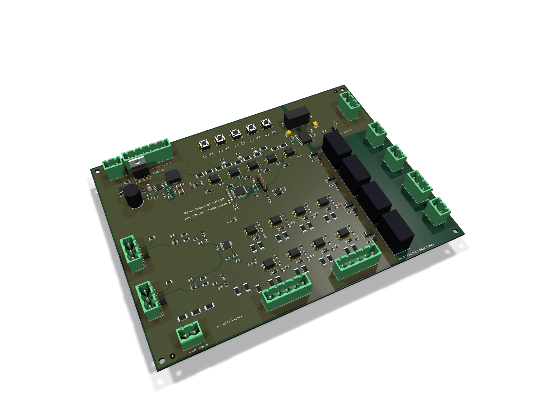
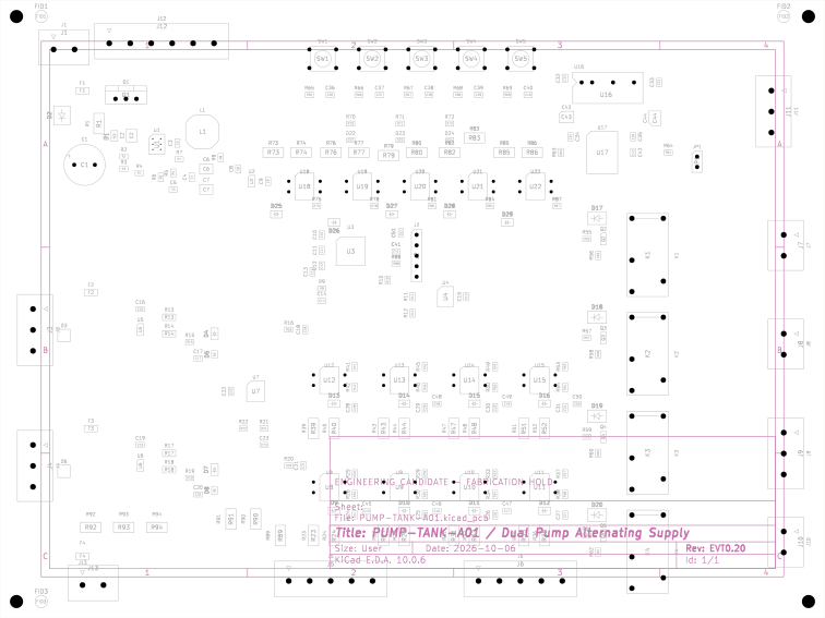
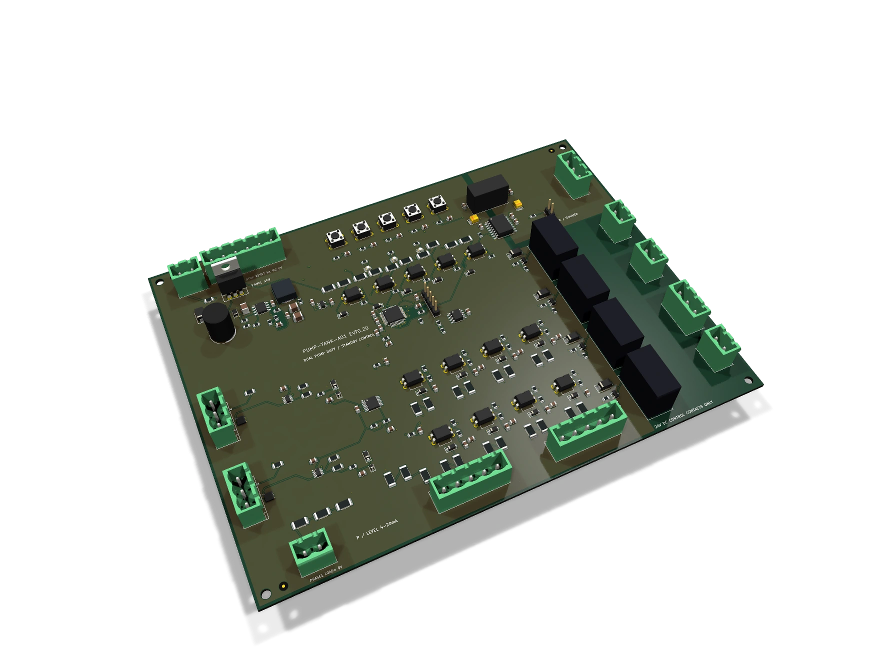
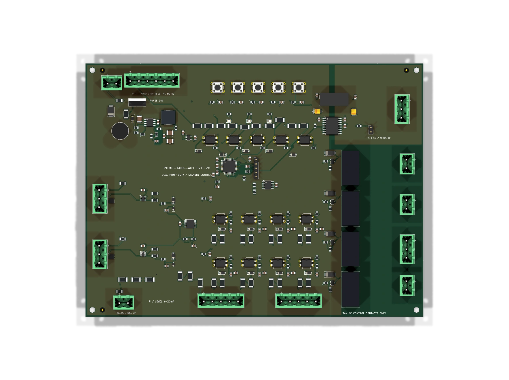
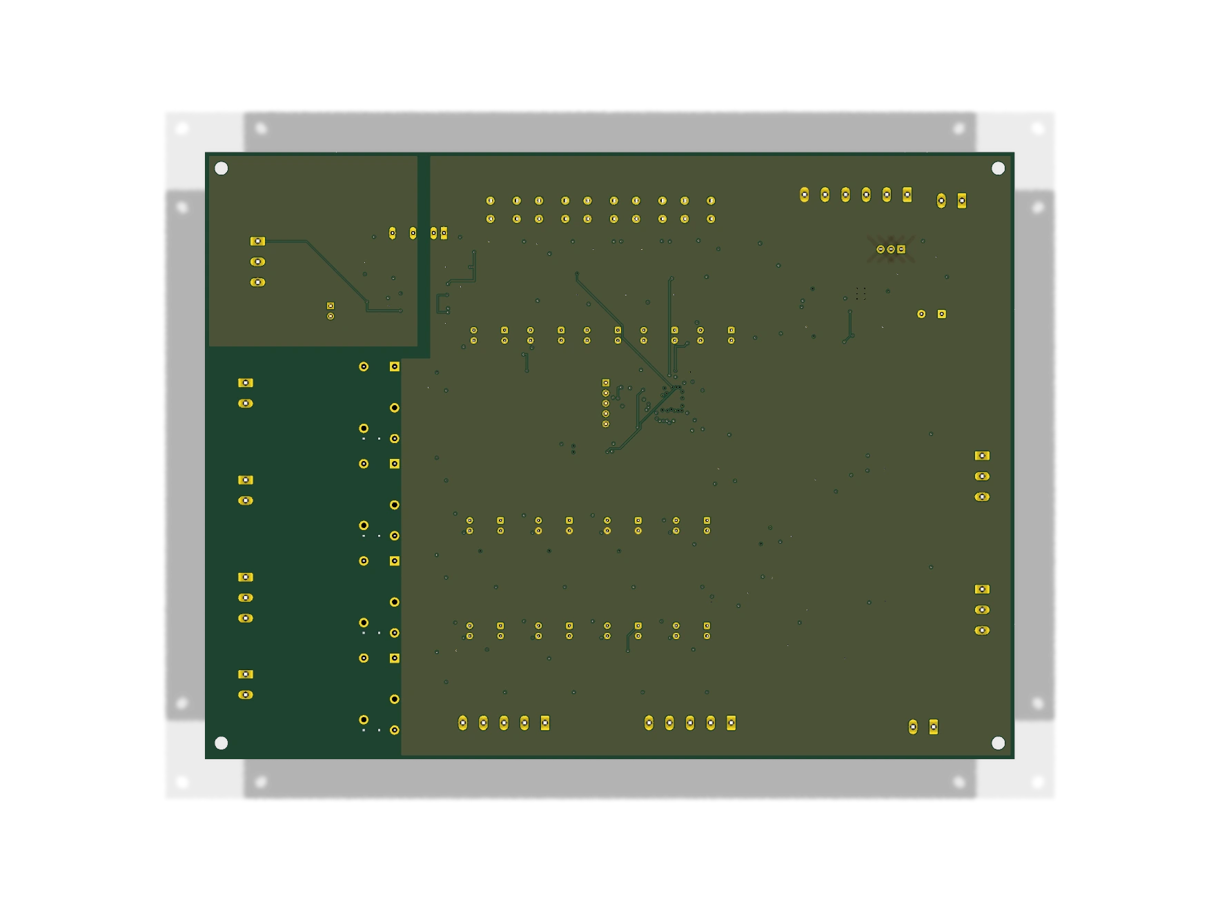
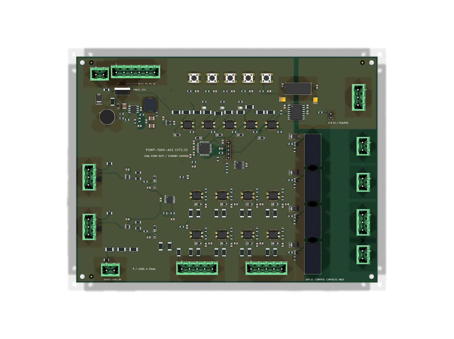
Generated from the KiCad PCB project and component geometry models. Inspect the component layout, connector orientation, mounting holes and underside. Open any image for the full-resolution view.
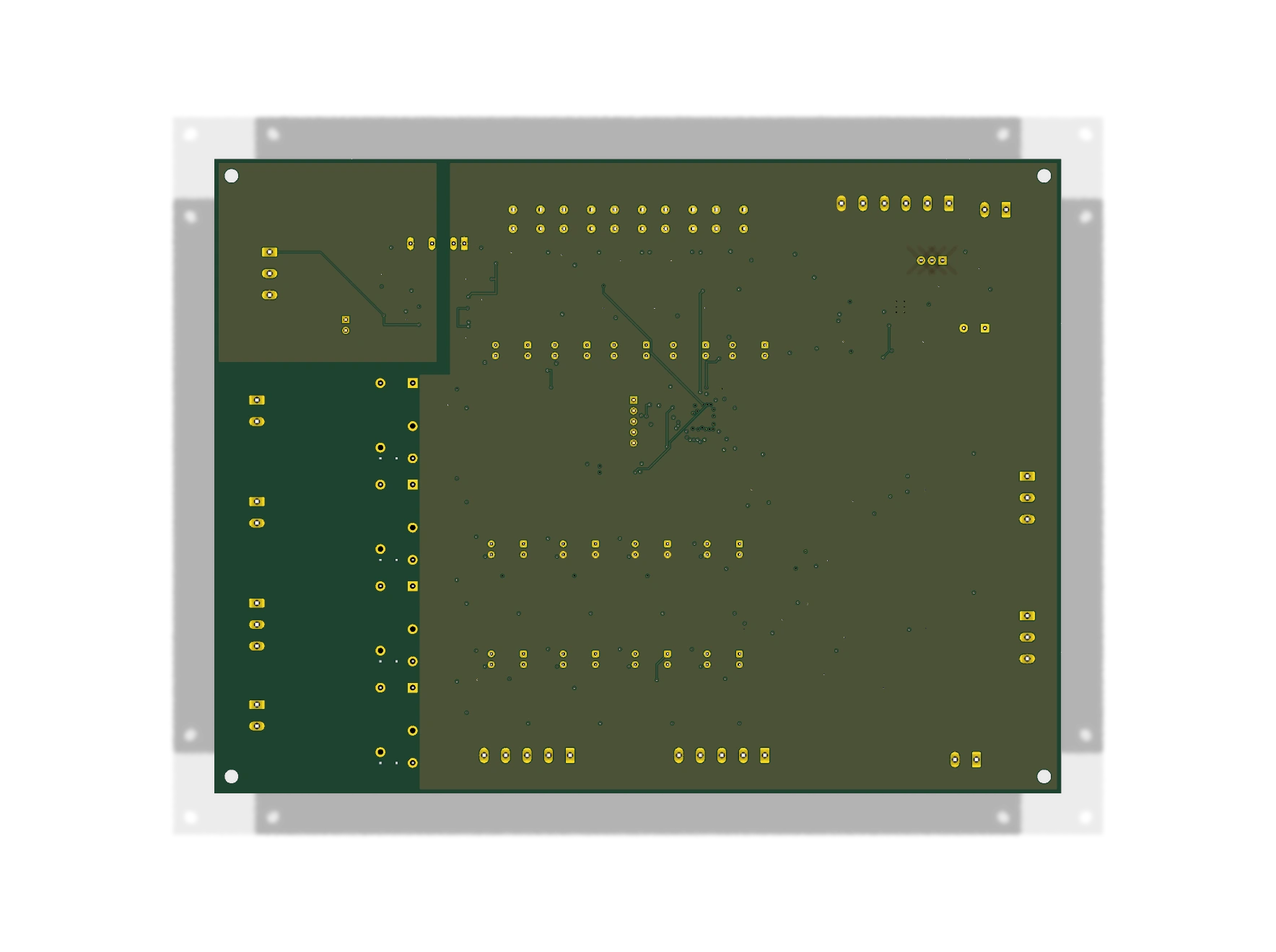
Designed around indoor clean-water auxiliary supply and direct-on-line contactor control. Match the pump curve, source-water level, system pressure and independent cabinet protection to the installation.
Integrate pressure control, alternation, contactor feedback and local operating records into a packaged two-pump supply unit.
Coordinate source-tank level and delivery pressure. A low-level input inhibits pumping, while pressure hysteresis reduces unnecessary switching.
Control clean-water feed and transfer auxiliaries. Independent level, pressure and motor-protection contacts remain in the cabinet.
Provide local on/off pressure control for clean-water utility skids, with one pump operating and the other available for alternate duty.
Give maintenance teams local fault indications, accumulated runtime, starts and Modbus access to pump-set information.
Reuse suitable contactors, overload devices and hardwired interlocks, adapting the field wiring and parameter settings to the existing installation.
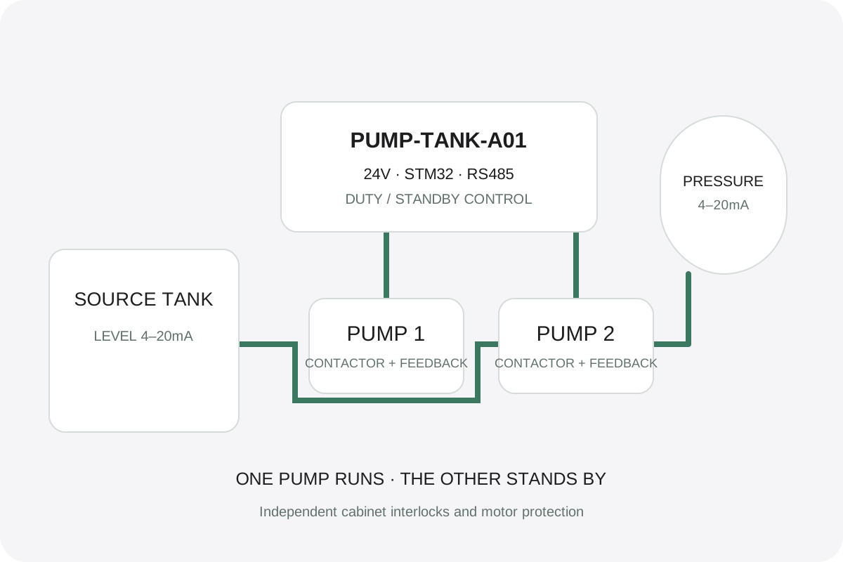
24V powers the controller and low-voltage cabinet branches. Two 4–20mA channels acquire pressure and tank level; 24V digital inputs acquire permissions, feedback and overload contacts. Dry-contact outputs command external 24V DC contactor coils. Motor power remains in the cabinet.
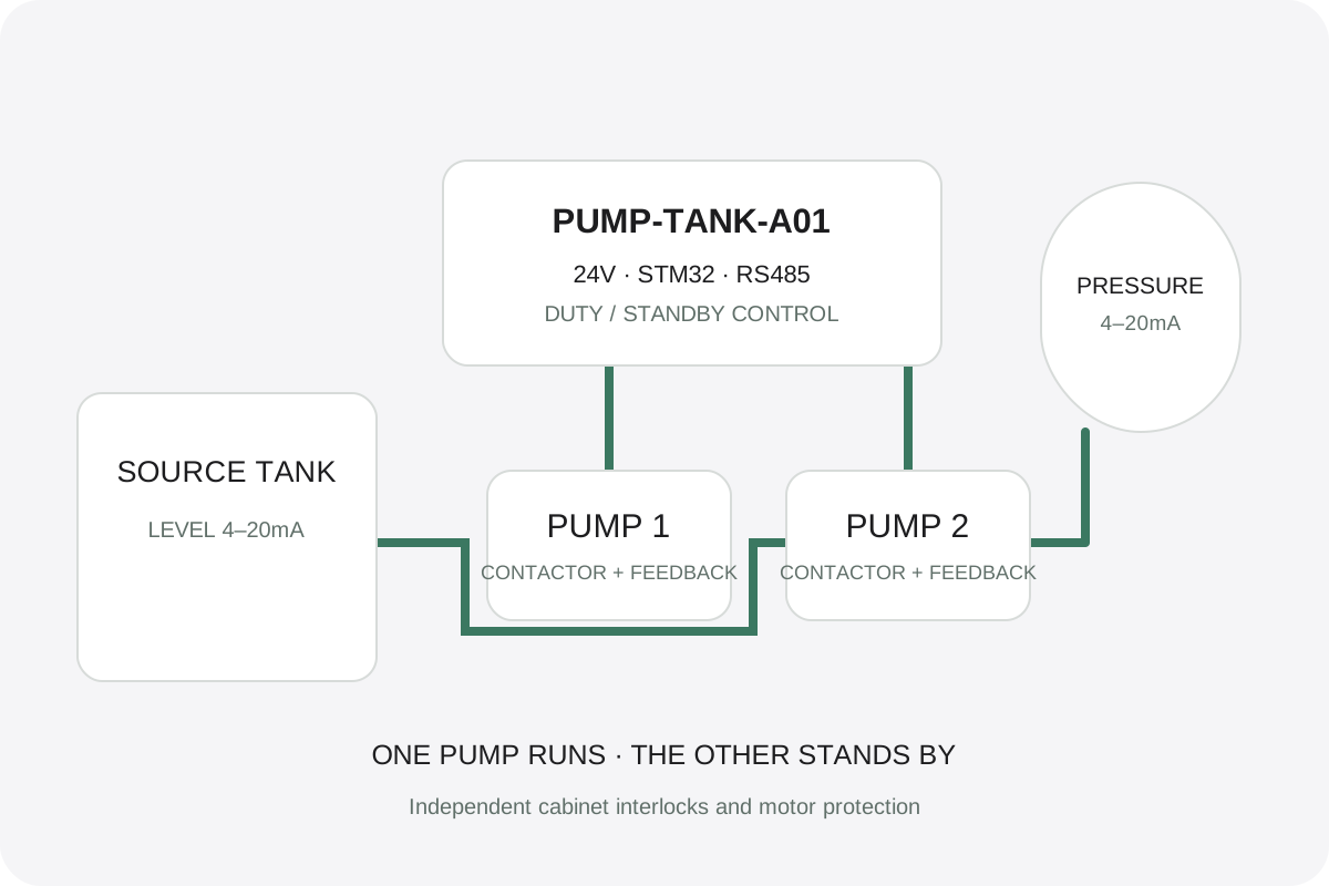
Successful operating cycles alternate duty between pump 1 and pump 2; only one pump is commanded at a time.
Automatic operation can transfer to the available standby pump after a start failure or overload, respecting the full stop interval.
The baseline starts below 2bar and stops at 3bar. Settings are matched to the hydraulic system; this is on/off control.
The baseline stop interval is 30s, feedback confirmation 2s and pressure-rise observation 10s.
Low source level, overpressure, invalid or stale measurements, contactor feedback faults and storage faults inhibit operation.
Manual commands retain protections. Reset clears an eligible latched fault; a separate new enable command is required to run.
Check independent protection, source water, sensors, contactor feedback and storage before accepting an automatic enable command.
Start the available duty pump below the start-pressure threshold after the required stop interval.
Check contactor feedback and pressure rise. Stop and mark the pump unavailable after a start failure or overload.
In automatic mode, start an available standby pump after the full stop interval. The controller never commands both pumps together.
Withdraw the pump command at the stop threshold; alternate duty after a successful supply cycle.
Protections remain active. Clear an eligible latched fault after its cause is removed; issue a new enable command to resume.
| Parameter | Baseline |
|---|---|
| Start / stop pressure | 2 / 3 bar |
| Minimum stop interval | 30 s |
| Contactor feedback confirmation | 2 s |
| Pressure-rise observation | 10 s |
| Simultaneous run commands | One pump maximum |
| Reset & power-up | Do not restore enable |
| Condition | Response |
|---|---|
| Low source / mechanical pressure / emergency stop / phase | Independent cabinet contacts interrupt execution branches; the controller monitors permission. |
| Motor overload / start failure | Withdraw the affected pump command; conditional standby transfer in automatic mode. |
| Invalid / stale analog measurement | Inhibit operation; read validity flags together with raw values. |
| Unexpected feedback / storage fault | Latch outputs off; retain available fault information and apply fault-specific reset conditions. |
The board uses STM32G071CBT6, a 24V input power stage, two protected current-loop inputs, isolated RS485, local buttons and nonvolatile storage. Download the fixed component selections and editable KiCad source.
228 electrical components · 59 MPNs · 189 SMT / 39 THT · 12 mating plugs
Follow the signal path from field inputs through the controller to external contactor commands, with the motor power circuit located in the cabinet.
| Area | Components / interfaces | Purpose |
|---|---|---|
| 24V power & input protection | J1 · F1 · Q1 · LM5164 · AP2112 | 18–30V input feeds 5V / 3.3V rails, with fuse, reverse-polarity and surge-protection components in the input branch. |
| Pressure & level acquisition | J3/J4 · TPS26611 · TVS3301 · TLV9004 | Two protected, filtered and conditioned 4–20mA channels feed the MCU; calibrate zero and full scale separately. |
| Field digital inputs | J5/J6/J12/J13 · LTV-817-C | Run permission, source level, pressure, overload, contactor feedback and cabinet-door commands. |
| Control & storage | STM32G071CBT6 · 24LC256 · J2 | Control state machine, persistent parameters and events; SWD firmware programming and debugging. |
| External commands & alarm | G5Q-14 DC5 × 4 · J7/J8/J9/J10 | Relay contacts connect low-voltage control branches to external contactors and independent protection contacts. |
| Industrial communication | ADM2795E · J11 · JP1 | Isolated RS485 for Modbus RTU; configure termination according to bus position. |
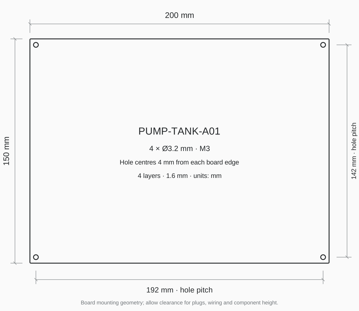
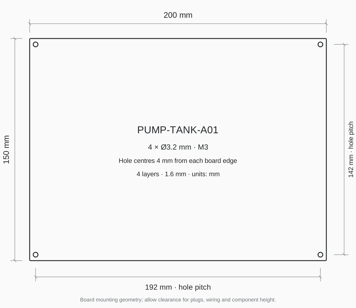
The board is 200 × 150mm, 1.6mm thick, with four Ø3.2mm holes for M3 mounting. Hole-centre pitch is 192 × 142mm; each centre is 4mm from its adjacent edges. Reserve cabinet space for mating plugs, cable bends, component height and service access.
| Connector | Pins | Function |
|---|---|---|
| J1 | 2 | 18–30V DC input |
| J2 | 5 | 3.3V-reference SWD |
| J3 / J4 | 3 each | Pressure / level 4–20mA loops |
| J5 / J6 | 5 each | Permission, source, pressure, feedback, overload, remote inputs |
| J7 / J8 | 2 each | Pump 1 / pump 2 dry contacts |
| J9 | 3 | Alarm changeover contact |
| J10 | 2 | Spare dry contact K4 COM / NO |
| JP1 | 2 | RS485 termination jumper |
| J11 | 3 | RS485 A / B / isolated reference |
| J12 | 6 | Cabinet control / STOP-health wiring |
| J13 | 2 | Independent first-phase-contact load branch |
Use the pin-by-pin connector table and cabinet wiring guide. The PCB contacts switch 24V DC control coils; they do not switch the motor supply. Preserve the independent emergency-stop, phase, source-level, mechanical pressure and overload chain, plus contactor interlocking.
| Connector | Pin | Net |
|---|---|---|
| J1 | 1 | VIN_RAW |
| J1 | 2 | GND |
| J2 | 1 | +3V3 |
| J2 | 2 | SWDIO |
| J2 | 3 | SWCLK |
| J2 | 4 | NRST |
| J2 | 5 | GND |
| J3 | 1 | LOOP_PWR_P |
| J3 | 2 | AI_IN_P |
| J3 | 3 | GND |
| J4 | 1 | LOOP_PWR_L |
| J4 | 2 | AI_IN_L |
| J4 | 3 | GND |
| J5 | 1 | DI_PERMIT_FIELD |
| J5 | 2 | DI_SOURCE_FIELD |
| J5 | 3 | DI_PRESSURE_FIELD |
| J5 | 4 | DI_FB1_FIELD |
| J5 | 5 | GND |
| J6 | 1 | DI_FB2_FIELD |
| J6 | 2 | DI_OL1_FIELD |
| J6 | 3 | DI_OL2_FIELD |
| J6 | 4 | DI_REMOTE_FIELD |
| J6 | 5 | GND |
| J7 | 1 | K1_COM |
| J7 | 2 | K1_NO |
| J8 | 1 | K2_COM |
| J8 | 2 | K2_NO |
| J9 | 1 | K3_COM |
| J9 | 2 | K3_NO |
| J9 | 3 | K3_NC |
| J10 | 1 | K4_COM |
| J10 | 2 | K4_NO |
| JP1 | 1 | TERM_B |
| JP1 | 2 | RS485_B |
| J11 | 1 | RS485_A |
| J11 | 2 | RS485_B |
| J11 | 3 | ISO_GND |
| J12 | 1 | PANEL_AUTO |
| J12 | 2 | PANEL_STOP |
| J12 | 3 | PANEL_RESET |
| J12 | 4 | PANEL_MAN1 |
| J12 | 5 | PANEL_MAN2 |
| J12 | 6 | GND |
| J13 | 1 | PHASE_CHAIN_FIELD |
| J13 | 2 | GND |
Modbus RTU runs at 9600baud, 8E1, default slave 1. FC03 reads values, parameters and event data; FC06 queues control commands; FC16 writes complete parameter groups and the event selector. Unavailable pressure/level values are reported as null by the service client, with raw words and per-channel validity.
Nonvolatile records include configuration, pump starts, accumulated runtime, boot count and a 464-entry event ring. Event timing uses monotonic uptime plus boot count. Power-up does not restore an enable command.
Addresses below are zero-based PDU addresses. Human register numbering is 40001 + PDU address; see the protocol download for byte order and complete fields.
| Function | PDU address | Purpose |
|---|---|---|
| FC03 | 0–31 | Status, measurements and operating statistics |
| FC03 | 256–268 | 13 configuration registers |
| FC06 | 288 | 1 Auto / 2 Stop / 3 Reset / 4 Manual P1 / 5 Manual P2 |
| FC16 | 256–268 | Complete parameter-group write; requires stopped and disabled conditions |
| FC16 | 512–513 | Set the 32-bit event selector |
| FC03 | 528–547 | Read the selected event and found flag |
Default 9600baud, 8E1, slave 1. A write echo confirms queuing; read state, enable and fault flags to confirm execution. Use RS485 on a tracked cabinet bus.
The reference system selects two Grundfos CM5-5 pumps, Schneider LC1D09BL 24V DC contactors, GV2L08 / LRD08 motor protection, RM17TG20 phase monitoring, WIKA A-10 pressure and LH-10 level transmitters, and a MEAN WELL HDR-100-24 control supply. The system BOM includes valves, tank, vessel, wiring and installation accessories.
Board outline: 200×150mm, four copper layers, 1.6mm high-Tg FR-4 and ENIG. SMT and THT coordinates are separated. The DFM files specify a 0.125mm stencil and six U1 filled, planarized, copper-capped thermal holes. Use the board drawings for mounting, polarity, pin 1 and conductor separation.
| Item | Specification |
|---|---|
| FR-4 | Tg ≥ 170°C · 4 layers · 1.6 ± 0.1mm |
| Copper | Outer ≥ 35µm · inner nominal 35µm |
| ENIG | Ni 3–6µm · Au 0.05–0.10µm |
| Stencil | 0.125mm · laser cut / electropolished |
| U1 | 6 filled / planarized / copper-capped thermal holes |
| Assembly | 189 SMT / 39 THT · separate placement files |
Electrical scaling is 0–10bar pressure and 0–100% level. Calibration coefficients reside in firmware Flash, separately from EEPROM operating parameters. Download the firmware package for full procedures and tools.
Keep pumping disabled. Apply 4 / 8 / 12 / 16 / 20mA to each channel and acquire at least 10 valid samples at distinct times per point.
Use calibrate_analog.py for a board-specific coefficient header and report. Fit 4 / 20mA; independently check 8 / 12 / 16mA.
Rebuild the matching firmware with the coefficient header, program and read back, then use new samples to check engineering values and out-of-range responses.
| Category | Reference selection | Integration point |
|---|---|---|
| Two pumps | Grundfos CM5-5 × 2 | Match the pump curve to required head, flow and hydraulic losses. |
| Contactors | Schneider LC1D09BL · 24V DC | Dry contacts command coils; retain hardwired pump interlocking. |
| Motor protection | GV2L08 / LRD08 | Set protection to the motor nameplate and coordination requirements. |
| Phase monitor | RM17TG20 | Connect to the independent permission branch. |
| Pressure / level | WIKA A-10 / LH-10 · 4–20mA | Select ranges for working pressure, tank height and wiring arrangement. |
| Control supply | MEAN WELL HDR-100-24 | 24V DC with separate controller and execution-branch protection. |
Adapt board dimensions, connector positions, sensor count and communication to the cabinet, with pin assignments and mating-plug selections.
Define pressure and timing parameters, manual / automatic behavior, Modbus addressing, event display and equipment-specific fault responses.
KiCad schematic / PCB, component BOM, manufacturing and assembly files, firmware source / HEX / BIN, protocol, wiring, calibration and DFM documents.
The published wiring and calibration instructions retain open bench, risk-review and response-testing items. Review these before build release. Download the complete technical archive or individual categories without registration. Files cover editable schematics and PCB, local libraries, component and system BOMs, Gerber/drill/placement data, firmware source and binaries, service tools, calibration, wiring and engineering records.
Download the 3D images and mounting drawing separately. The existing complete engineering archive remains available.
Send the water-supply arrangement, pump and contactor details, pressure/level ranges, cabinet interfaces, board dimensions and required quantities to define your OEM controller scope.
Discuss pump controller development ↗