Pump equipment OEM
Integrate pressure control, alternation, contactor feedback and local operating records into a packaged two-pump supply unit.
PUMP-TANK-A01 · WATER CONTROL
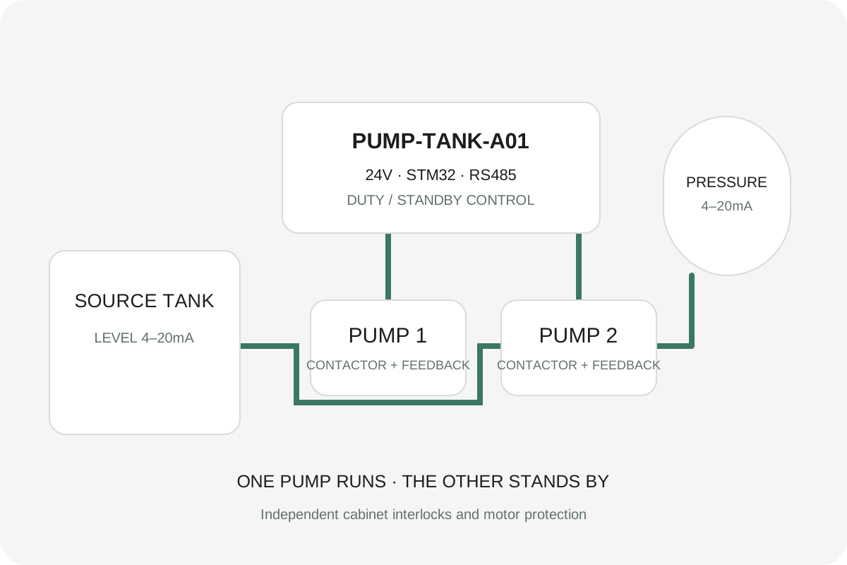
A duty/standby controller for pump manufacturers, water-treatment equipment and cabinet integrators. Pressure and tank-level inputs coordinate one running pump and one standby pump, automatic alternation, fault handling and operating records.
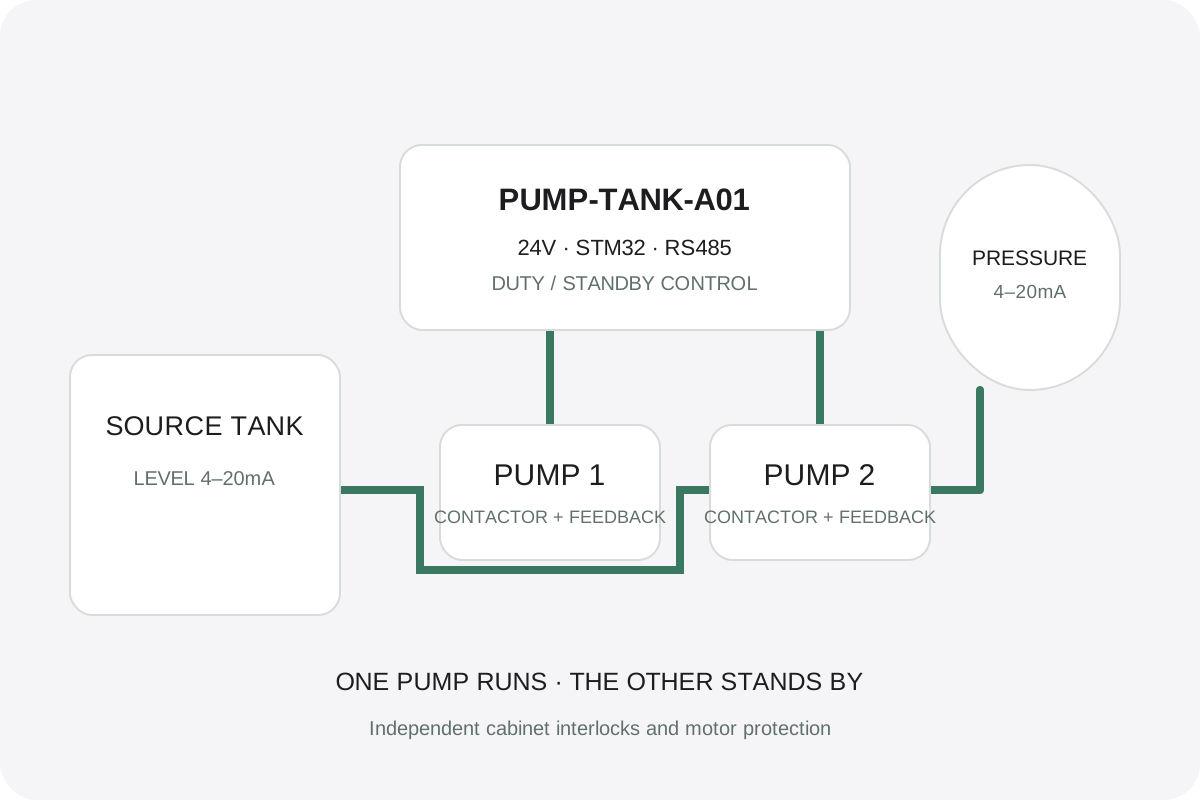
Designed around indoor clean-water auxiliary supply and direct-on-line contactor control. Match the pump curve, source-water level, system pressure and independent cabinet protection to the installation.
Integrate pressure control, alternation, contactor feedback and local operating records into a packaged two-pump supply unit.
Coordinate source-tank level and delivery pressure. A low-level input inhibits pumping, while pressure hysteresis reduces unnecessary switching.
Control clean-water feed and transfer auxiliaries. Independent level, pressure and motor-protection contacts remain in the cabinet.
Provide local on/off pressure control for clean-water utility skids, with one pump operating and the other available for alternate duty.
Give maintenance teams local fault indications, accumulated runtime, starts and Modbus access to pump-set information.
Reuse suitable contactors, overload devices and hardwired interlocks, adapting the field wiring and parameter settings to the existing installation.
24V powers the controller and low-voltage cabinet branches. Two 4–20mA channels acquire pressure and tank level; 24V digital inputs acquire permissions, feedback and overload contacts. Dry-contact outputs command external 24V DC contactor coils. Motor power remains in the cabinet.
Successful operating cycles alternate duty between pump 1 and pump 2; only one pump is commanded at a time.
Automatic operation can transfer to the available standby pump after a start failure or overload, respecting the full stop interval.
The baseline starts below 2bar and stops at 3bar. Settings are matched to the hydraulic system; this is on/off control.
The baseline stop interval is 30s, feedback confirmation 2s and pressure-rise observation 10s.
Low source level, overpressure, invalid or stale measurements, contactor feedback faults and storage faults inhibit operation.
Manual commands retain protections. Reset clears an eligible latched fault; a separate new enable command is required to run.
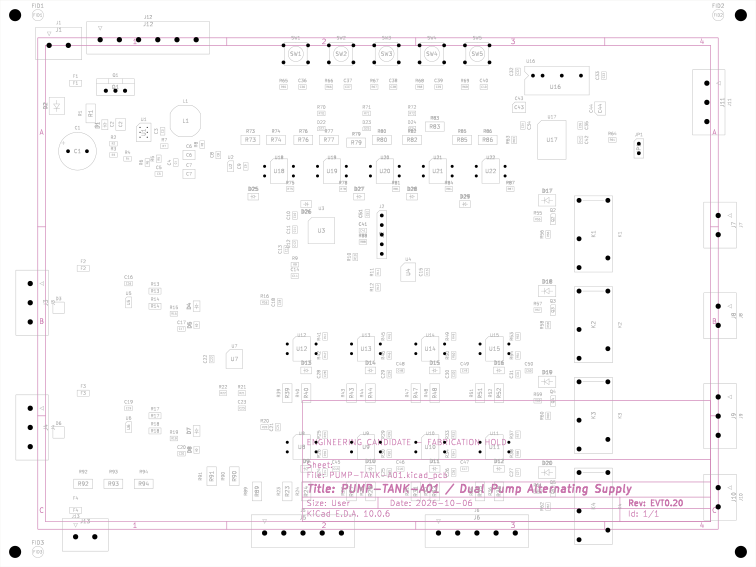
The board uses STM32G071CBT6, a 24V input power stage, two protected current-loop inputs, isolated RS485, local buttons and nonvolatile storage. Download the fixed component selections and editable KiCad source.
228 electrical components · 59 MPNs · 189 SMT / 39 THT · 12 mating plugs
| Connector | Pins | Function |
|---|---|---|
| J1 | 2 | 18–30V DC input |
| J2 | 5 | 3.3V-reference SWD |
| J3 / J4 | 3 each | Pressure / level 4–20mA loops |
| J5 / J6 | 5 each | Permission, source, pressure, feedback, overload, remote inputs |
| J7 / J8 | 2 each | Pump 1 / pump 2 dry contacts |
| J9 | 3 | Alarm changeover contact |
| J11 | 3 | RS485 A / B / isolated reference |
| J12 | 6 | Cabinet control / STOP-health wiring |
| J13 | 2 | Independent first-phase-contact load branch |
Use the pin-by-pin connector table and cabinet wiring guide. The PCB contacts switch 24V DC control coils; they do not switch the motor supply. Preserve the independent emergency-stop, phase, source-level, mechanical pressure and overload chain, plus contactor interlocking.
Modbus RTU runs at 9600baud, 8E1, default slave 1. FC03 reads values, parameters and event data; FC06 queues control commands; FC16 writes complete parameter groups and the event selector. Unavailable pressure/level values are reported as null by the service client, with raw words and per-channel validity.
Nonvolatile records include configuration, pump starts, accumulated runtime, boot count and a 464-entry event ring. Event timing uses monotonic uptime plus boot count. Power-up does not restore an enable command.
The reference system selects two Grundfos CM5-5 pumps, Schneider LC1D09BL 24V DC contactors, GV2L08 / LRD08 motor protection, RM17TG20 phase monitoring, WIKA A-10 pressure and LH-10 level transmitters, and a MEAN WELL HDR-100-24 control supply. The system BOM includes valves, tank, vessel, wiring and installation accessories.
Board outline: 200×150mm, four copper layers, 1.6mm high-Tg FR-4 and ENIG. SMT and THT coordinates are separated. The DFM files specify a 0.125mm stencil and six U1 filled, planarized, copper-capped thermal holes. Use the board drawings for mounting, polarity, pin 1 and conductor separation.
Download the complete technical archive or individual categories without registration. Files cover editable schematics and PCB, local libraries, component and system BOMs, Gerber/drill/placement data, firmware source and binaries, service tools, calibration, wiring and engineering records.
Send the water-supply arrangement, pump and contactor details, pressure/level ranges, cabinet interfaces, board dimensions and required quantities to define your OEM controller scope.
Discuss pump controller development ↗